|
SKETCH NAME |
DESCRIPTION & LEARNINGS |
SOURCE LINKS |
SUPPLEMENTAL INFO |
|
|
Digital pins 2 through 8 are assigned to LED segments 'a' through 'g'; we're not going to use the dp (decimal point). A function or procedure, e.g., 'zero()', is created for each number from `0` to `9' and each of the 7 segments is enabled or disabled for the number. In the main loop, each function is called in turn, including 'blank()' that runs at the end of the count from '0' to '9'.
|
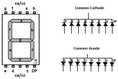
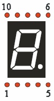
How to use a 7-segment display Connecting a 7-segment LED display to an Arduino, Part 1 Datasheet 5101AS 7-segment LED display. |
A 7-segment LED display is connected directly to Arduino using 7 pins: The common cathode (CC) pin is connected to ground via a current limiting resistor. For the number '0' to be illuminated with a CC device, all segments except 'g' are selected and sent a HIGH signal; 'g' is sent a LOW signal. For CA, the opposite is true: all of the signals are complementary compared to CC.
|
|
|
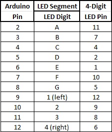
Connect a 4-digit 7-segment LED display to Arduino. Each digit has its own enable/common pin to enable just that digit. If we used 4 separate LED digit displays, we would need to connect all of the 'a' segments together, all of the 'b' segments, etc. This quad package performs that function, reducing the pin count substantially. In the sketch, the character, e.g., '0' to be displayed will be sent to all of the digits simultaneously but only the left-most digit with the common pin asserted will display the '0'. Then a '1' will be displayed on all of the digits simultaneously but only the second-from-the-left digit's common pin will be asserted, etc. The 'delay()' time for each digit's display is set to a very low (1ms) value, and then the code moves to the next digit block. This is a form of multiplexing that makes it appear as though the number '0' is only displayed on the first digit, only the number '1' on the second digit, etc. |
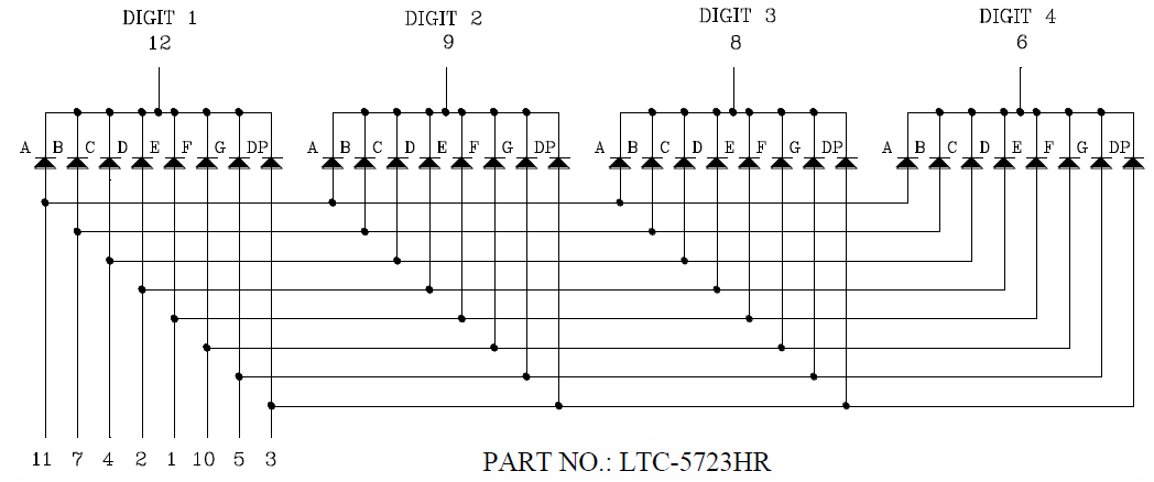
Connecting a 7-segment LED display to an Arduino, Part 2. Datasheet LTC-5723HR 7-segment 4-digit common cathode display. A direct connection to a 4-digit display will use 7 segment pins and 4 digit pins for a total of 11 Arduino pins!
|
Common Cathode pinout for LTC-5723HR 7-segment 4-digit LED display:
|
|
7-Segment_4-Digit_LED_CC_74595.ino 7-Segment_4-Digit_LED_CC_74595a.ino
|
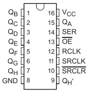
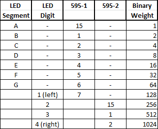
LEDs take up too many of Arduino's I/O pins. The 74595 8-bit Shift Register can reduce the pin count to just 3: SerialClock, Data, and Latch. The 74595 contains an 8-bit, serial-in/parallel-out shift register that feeds an 8-bit D-type storage register. Using the table below and to the right, we transfer a decimal value to the '595 which outputs a binary value to all of the LED segments we wish to display/not display. The operation is: - Write the Latch low - Shift out the decimal value as a binary stream to the '595 - Write the Latch high The data is not displayed until the Latch is set high by Arduino. In common cathode (CC), all of the LED segments require a positive voltage on the anode (+) side of each diode to illuminate them. All of the cathode (-) sides of each diode are tied together to a common point and ground, hence the name common cathode. In CC, the number to output a blank is '0' because no LED segments would be illuminated. |
Connecting a 7-segment LED display to an Arduino Part 3: Arduino connection via a 74HC595 shift register to a single digit display using just 3 pins.
7-Segment_4-Digit_LED_CC_74595a.ino This is a shorter version of the code, It uses an array for each numerical code used to display a 'blank' or a number from '0' to '9'. Array, 'CC[ ]', has 11 elements represented as 'CC[11]' and are numbered '0' to '10' for a total of 11. The array members are placed between parentheses as '{0,63,6,91,79,102,109,125,7,127,103}'. In the 'for' loop, the 'shiftOut' operation uses 'CC[i]' instead of the numerical value. This allows us to go through all of the numerical representations for 'blank' and '0' to '9' with the least amount of code. |
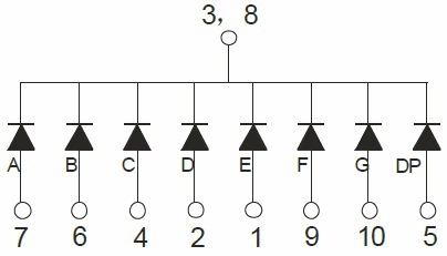
Pinout for 74595 shift register, a 7-segment LED display, and a common cathode config.
|
|
7-Segment_4-Digit_LED_CC_74595x2.ino
|
'595s can be daisy-chained. The first 7 output pins (Qa through Qg) of the '595 are connected to the corresponding A to G segment pins of the LED. The decimal point, DP, is not used. The binary weights are from 1 to 64 instead of 128 because the DP will not be used. Qh will have a binary weight of '128' and it will not be used for LED segments; it will be used as a digital select instead. To display the number '0' in CC, all but the 'G' segment are sent a binary '1'. The resultant decimal value is '63' as shown in the table. If we wish to display this value on the 1st digit, then '128' must be added to the value '63' for a total of '191'. However, if the LED is CC, then a LOW is needed instead of a HIGH to complete the circuit. The easiest way to accomplish this is to put a high on the three other digits which means a low on the first digit. Example 1: 'D2 + D3 + D4 + 0' will output a '0' on the first digit. Example 2: 'D1 + D3 + D4 + 0' will output a '0' on the second digit. |
Connecting a 7-segment LED display to an Arduino Part 4: Arduino connection via two 74HC595 shift registers to a 4-digit display using just 3 Arduino pins. CA: common anode CC: common cathode
CA and CC values for numbers 0 to 9
|
Connection Diagram for Arduino, two '595s, and 4-digit 7-segment LED display.
Complete schematic with Arduino Nano:
|
|
7-Segment_8-Digit_LED_Max7219.ino
|
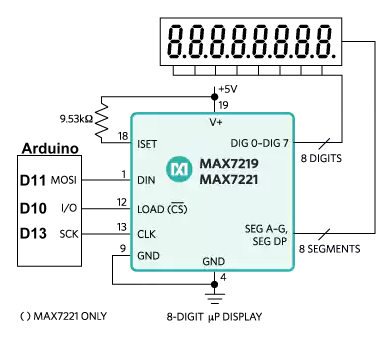
A single chip, MAX7219, drives the two quad-digit LED arrays. The 8-digit board uses SPI for 3-wire communication with an Arduino. The sketch makes use of the common high-speed hardware SPI pins: MOSI, SCLK and CS. The MAX7219 is limited to characters 0 to 9, HELP, and blank while in Decode mode. With this mode disabled, individual LED segments can be chosen to make your own limited set of characters like 'A', 'b', 'c', 'd', 'F', 'H', etc. A 'for' loop is used to clear all eight digits. Three procedures are written: 1) 'display' to 'shiftOut' the address and value to be written. 2) 'blankRow' to blank all 8 digits. 3) 'blankDigit' to blank a single digit.
The LEDs module used also contains a Load pin on the far right side that permits daisychaining two modules with separate CS/Load pins. |
Using a MAX7219 to drive 8 LED digits - Part 1, Part 2, and Part 3.
MAX7219 datasheet. MAX6950 supports 3.3v operation.
Maxim Integrated website link. Digikey link to MAX7219.
Github file repository.
MAX7219 Red 8-Bit Digital Tube LED Display Module - common-cathode, 3v/5v - SPI (SCLK, MOSI, CS) interface
Vendor: Banggood.com
|
MAX7219 schematic:
|