|
SKETCH NAME |
DESCRIPTION & LEARNINGS |
SOURCE LINKS |
SUPPLEMENTAL INFO |
|
|
When we left off with page 'SKETCHES: Graphic LCDs I', we were working
with the 3.3v (let's call it 3v3) Arduino Pro Mini and the 3v3 Nokia
5110 84w x 48h LCD graphic display. We used the
U8g2 library because it contained both a RAM-sparing text mode as well as
a very flexible graphics mode that will accommodate almost any LCD
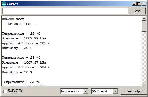
panel and controller. In this lab, we're going to continue using SPI for communication and work with the BME280 Temperature/Humidity/Baro Pressure/Altitude sensor. The Adafruit BME280 sensor supports both SPI and I2C communication and has built-in level shifting for 3v3 or 5v operation. Try the Adafruit bme280test.ino sketch found in the 'Examples' folder of the Adafruit_BME280 library. Note that is has not been configured for SPI. Alternatively, try this one which has been configured for SPI: BME280_Test.ino You will need the serial monitor to see the sensor working. Once you're done, try out Nokia-BME280.ino which combines the Nokia5110_U8G2_DrawRect.ino sketch with the BME280_Test-FB.ino sketch so you can observe the sensor working on the Nokia display instead of the serial monitor, as shown in the adjacent .gif file.
|
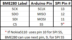
Adafruit BME280 pinout for SPI comm:
Adafruit BME280 Library installation slideshow
Repeat the actions above for 'Adafruit Unified Sensor'. instead of 'Adafruit BME280'. Bosch BME280 Datasheet, Adafruit BME280 Library1 U8G2 graphics drivers Frequently Asked Questions. |
Vendor 1: BME280 product
Vendor 2: BME280 product Vendor 2: Hookup Guide
Vendor 3: BME280 product
Here is some information on how to use millis() to invoke a function every elapsed time period. It's more efficient than delay() and is used in the Nokia-BME280.ino sketch: the BME is tested upon power up and then every 5 minutes. The user is advised if the sensor fails. In loop(), millis() is called twice. The first is the aforementioned 5-minute timer. The second is a 10-second timer to determine if there has been a change in barometric pressure - has it gone [U]p, [D]own, or is it the [S]ame which is displayed in the top center of the display over the one-second activity indicator.
|
|
|
RTC = Real Time Clock Only the more expensive RTCs support SPI comm so we'll stick with one of the less expensive ones that support I2C comm: PCF8523 or DS1307. Adafruit PCF8523 is the best 3v3 choice for Arduino Pro Mini or any newer 3v3 board. - PCF8523 RTC supports 3v3 or 5v, I2C comm. - DS1307 supports 5v, I2C comm. - IDE library: Sketch|Include Library|RTClib - RTClib supports DS1307, DS3231, and PCF8523.
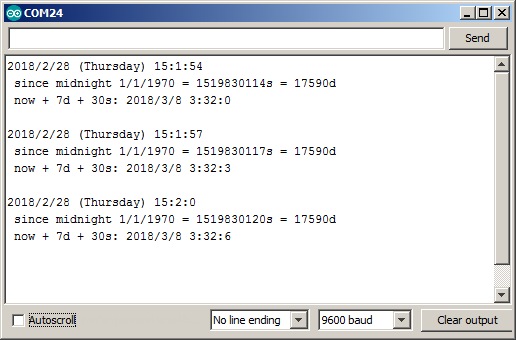
Try the adjacent pcf8523.ino sketch first with your serial monitor set to 9600. Then run it again after you have commented-out line 23 so that it won't use the internal PC clock, but instead will use its battery-saved clock. Confirm proper operation by hitting the Arduino Reset button and reconnecting the Serial Monitor app.
In the adjacent sketch, pcf8523-lean.ino, we have replaced the serial monitor code with LCD display code and added a few other cosmetic features. |
Vendor 1: PCF8523 RTC or DS1307 RTC w/ battery Vendor 2: DS1307 RTC w/ battery Vendor 3: DS1307 RTC w/ battery
|