|
SKETCH NAME |
DESCRIPTION & LEARNINGS |
SOURCE LINKS |
SUPPLEMENTAL INFO |
|
|
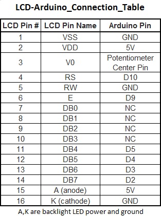
The 'LiquidCrystal.h' library is introduced and configured for this particular LCD panel. The library can be found in the Arduino IDE under 'Sketch|Include Library|Liquid Crystal'; clicking it will add the library to the top of your open sketch as '#include <LiquidCrystal.h>'.
The main loop has only two functions: to count from 0 to 10, and then from 10 to 0.
An additional counter uses the 'millis()' function to keep track of the number of seconds since the Arduino was reset.
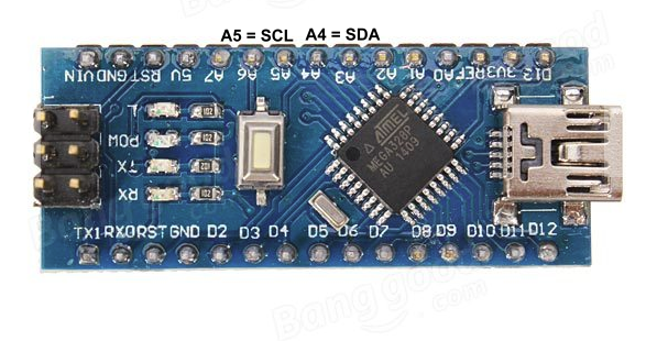
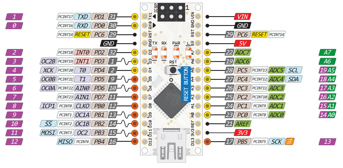
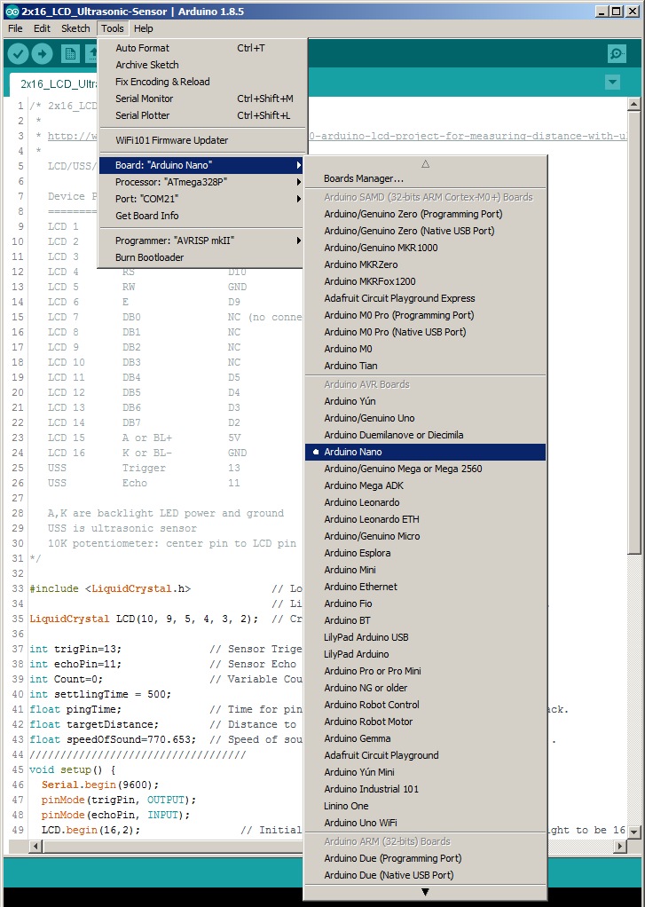
Arduino Nano has the same connectivity and specs of the UNO board but in a smaller form factor.
|
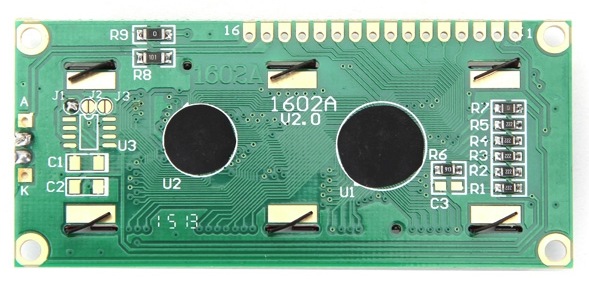
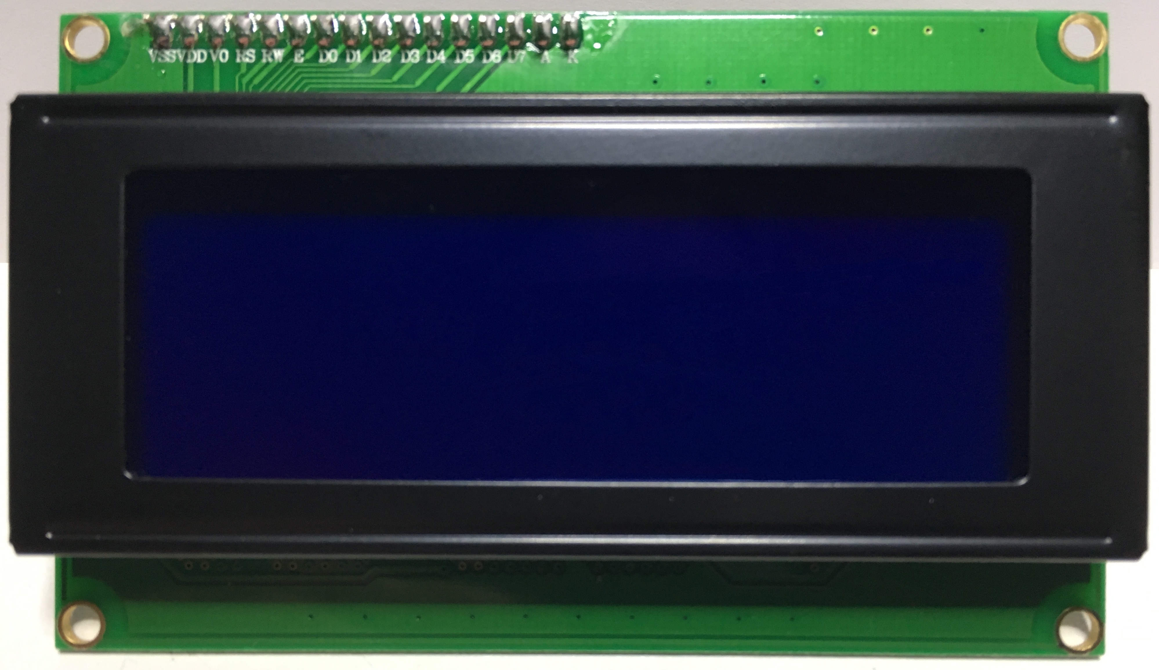
Video: Using LCD Display with Arduino. Display: a 1602-type Hitachi HD44780 controller based LCD panel is used. Vendors: Arduino Nano, 16x2 LCD
Arduino Nano Pinout Diagram
|
1602-type LCD display (click to enlarge)
Arduino Nano (5v)
|
|
16x2_LCD_Ultrasonic-Sensor.ino
|
Once the type 1602 parallel LCD 2x16 panel is hooked up to Arduino, an
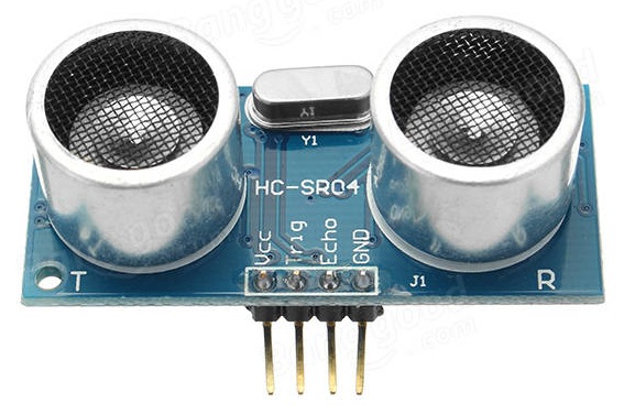
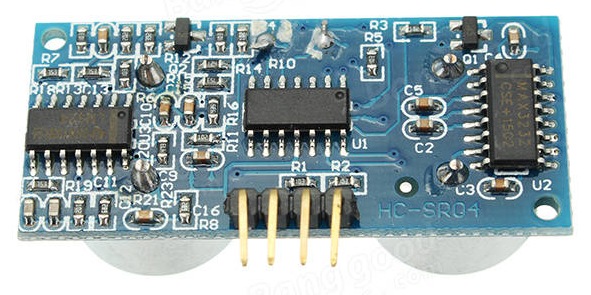
ultrasonic sensor is added to measure distances to nearby objects. In the adjacent .gif file, a roll of solder is moved towards the ultrasonic sensor and it's relative position is displayed every 1/2 second or so.
|
Measuring the speed of sound with Arduino and an ultrasonic sensor,
TopTechBoy Lesson 17, and then
measuring the distance to an object,
TopTechBoy Lesson 20. How To Mechatronics Youtube tutorial. Vendor: Ultrasonic Sensor HC-SR04. HC-SR04 Schematic.
|
HC-SR04 Ultrasonic Sensor
|
|
|
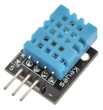
The ultrasonic sensor is replaced with a DHT11 temperature/humidity
sensor. The sketch starts off by testing the sensor, then displays temp and humidity on the LCD. If the sensor's Signal wire were disconnected prior to sketch start up or the Arduino is reset, the error will be revealed. If the sensor fails during normal operation, the temp and humidity values will be zero. Once the situation is corrected, normal display will resume. In the sketch, the sensor test 'testDHT' is conducted as a separate procedure using a 'switch-case' construct. These are often used for variable input statements, but in our case it's used to display the specific error code. |
How To Mechatronics Youtube
tutorial. Partial (adquate) DHT11 library. Full DHT11 library. DHT11 temperature/humidity sensor: Vendor 1, Vendor 2. DHT11 working principle. Attachment is simple: VCC, Gnd, Signal. Many vendors include a breakout board with the sensor that contains a 10K ohm pullup resistor from 'S' to VCC. The dht library needs to be placed in the standard libraries folder. Example: '..\My Documents\Arduino\libraries'. Info on installing libraries properly. |
DHT11 Temperature/Humidity Sensor
|
|
|
IIC or
I2C
communication is used between serial devices and Arduino. It uses SCL
(Arduino A5 pin) for control and SDA (Arduino A4 pin) for data.
Pull-up resistors (usually 4.7K or 10K)
should be used on these two pins for reliable operation; check if your
serial device already has them built in. The Wire.h library must be included at the beginning of the sketch in order for I2C to work: 'Sketch|Include Library|Wire'
|
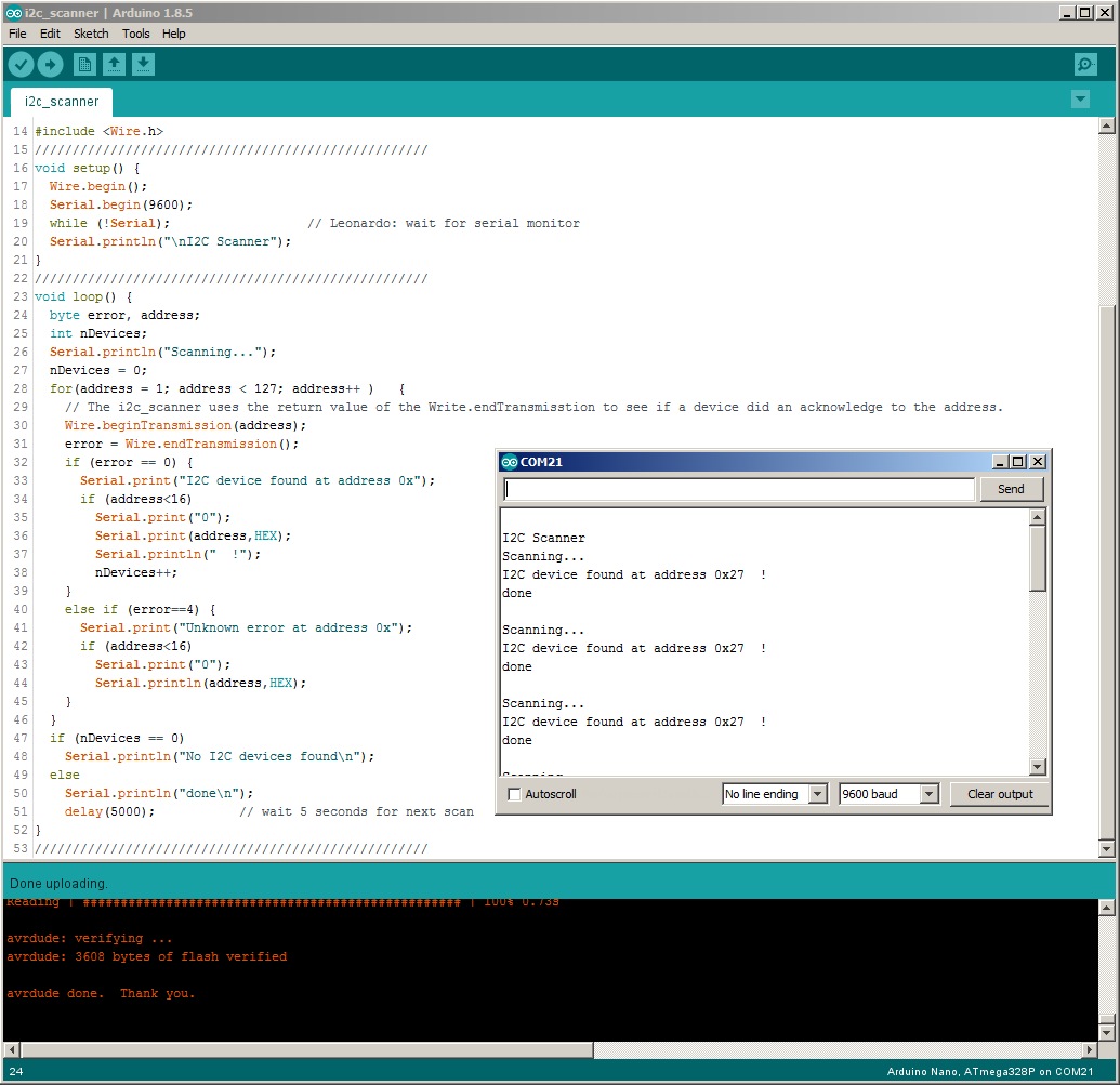
I2C Scanner
info.
I2C Bus
info. If you cannot get an I2C device to work, e.g., 'Hello World' won't display on your I2C LCD device, run the i2c_scanner.ino sketch with the Serial Monitor; it will tell you which I2C address is used by your device. Ideally, you want to try only one device (connected to your Arduino) so you can build an inventory of addresses used. I2C devices are uniquely identified by their addresses. Ensure your display's address does not conflict with other I2C devices connected to your Arduino. Some devices have PCB trace jumpers labeled A0 to A2 that you can modify (solder/jumper) to change its address. Adafruit I2C address list and address table. |
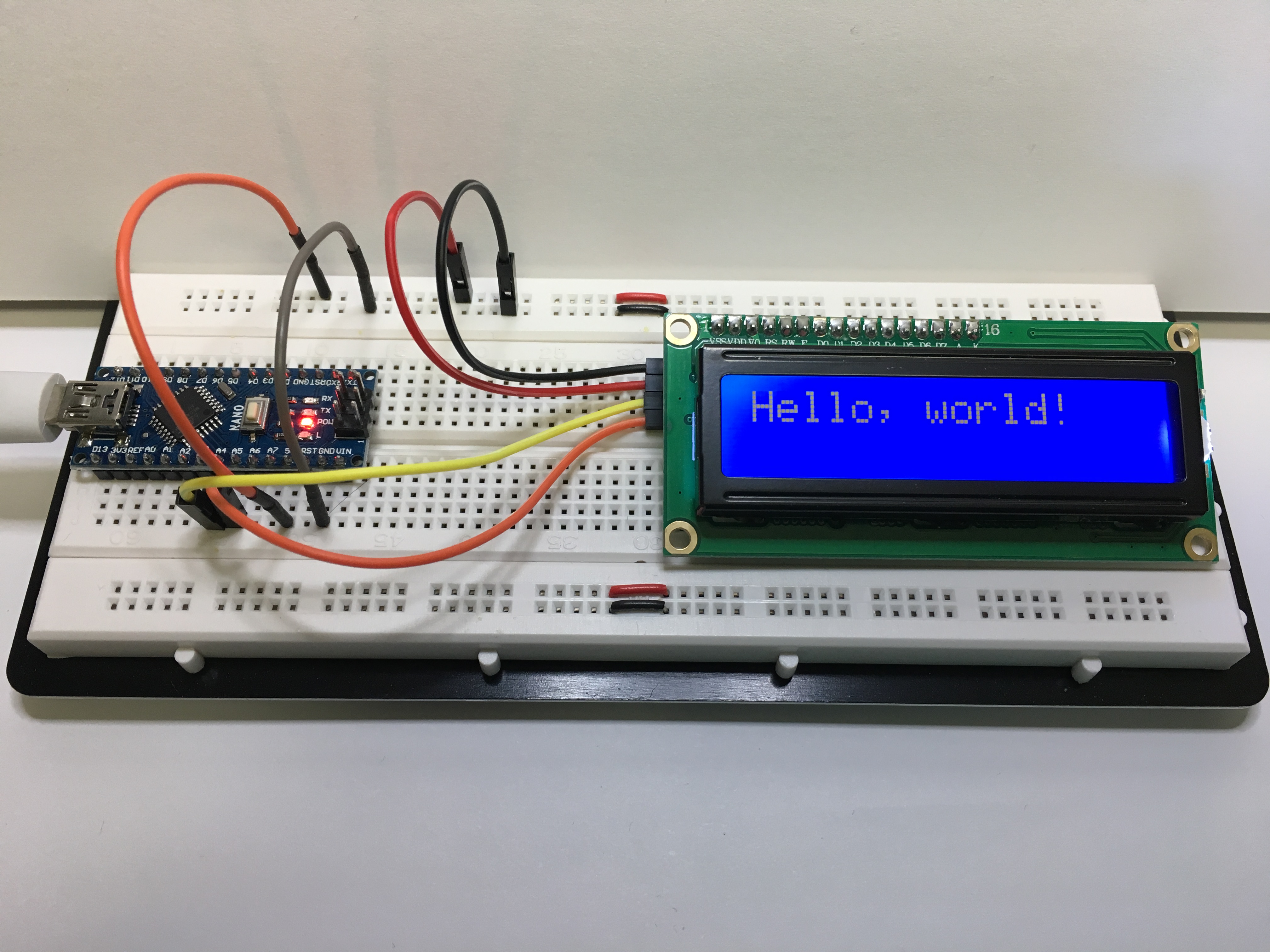
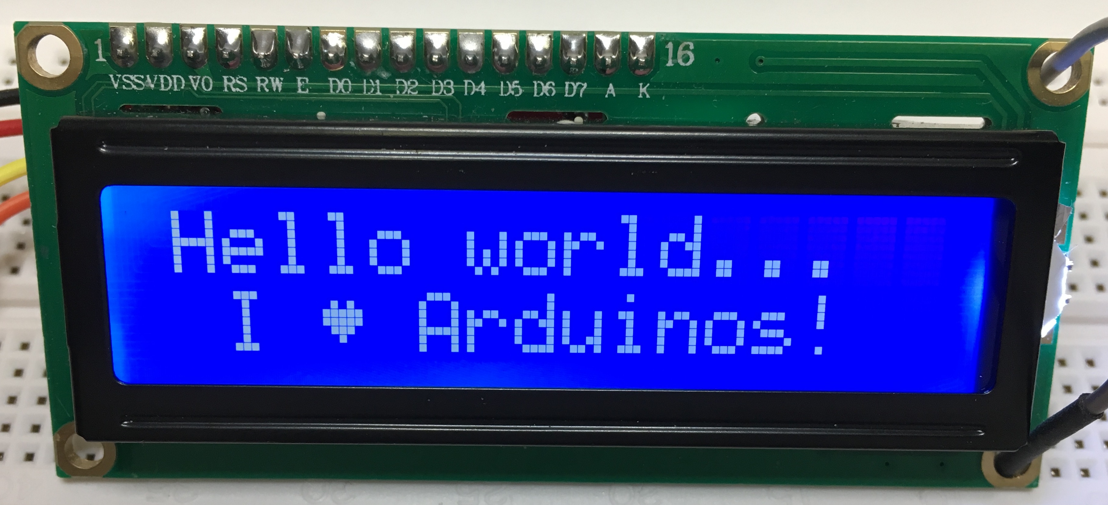
Hello World from I2C!
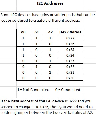
Changing I2C Addresses:
|
|
|
In addition to the
Wire.h library, you will also need the
LiquidCrystal_I2C library. Follow the
directions carefully in the
README.cmd file to install it. The
Funduino-based backpacks for LCD displays use I2C address 0x27, not 0x20
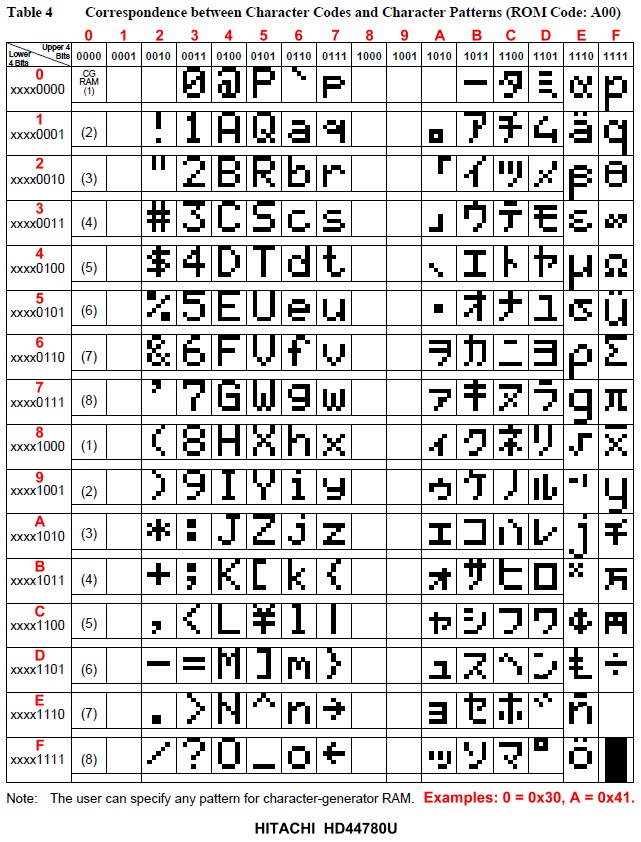
like some others. In addition to displaying standard ASCII characters to the 16x2 LCD screen, the LCD_Custom_LCD_Characters.ino sketch also displays 8 custom characters created using the lcd.createChar command. The character data is shown at the top of the sketch as 8-byte arrays that draw each of the 8 pixel rows that comprise the 5x8 cells (5 pixel width, 8 pixel height) of each character. |
Info on lcd.print((char)0) Basic info on creating custom LCD characters. Detailed info on creating custom LCD characters. In the LCD_Custom_LCD_Characters.ino sketch, Japanese characters are displayed. Hitachi HD44780U LCD character sets, both ASCII and Japanese character.
|
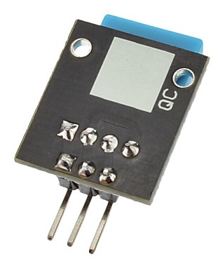
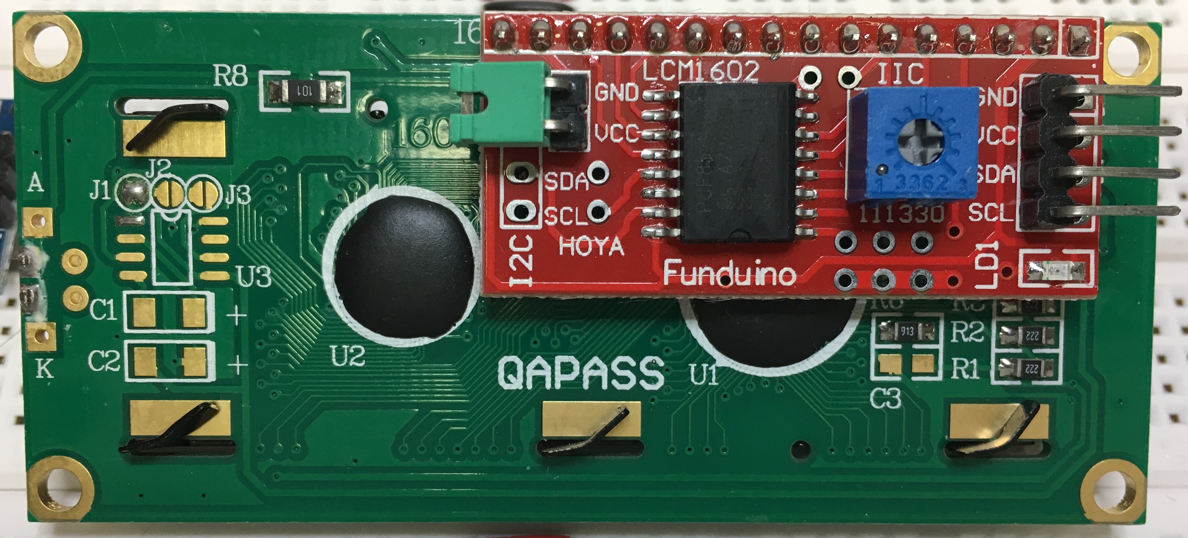
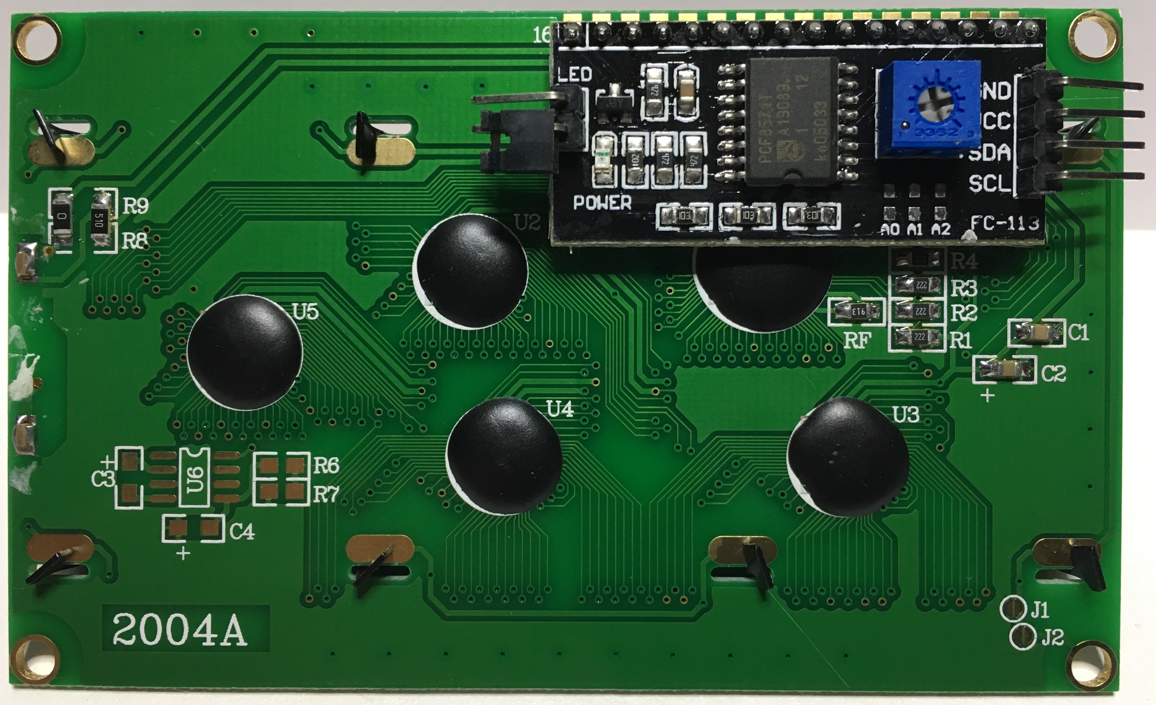
Hitachi HD44780 based,
1602-type (16x2) I2C Serial LCD:
Funduino 'backpack' attached to the parallel LCD panel provides I2C communication. Backlight-enable jumper is green, backlight contrast adjuster pot is blue.
The 6 solder pads (3 vertical pairs) beneath the blue pot in the bottom view are for adjusting the I2C address. Although the numbering cannot be seen, they are numbered A0 on the left to A2 on the right. Jumpering the pads vertically will change the default address from 0x27 to a value between 0x20 and 0x27. See chart above. |
|
LCD_Emojis.ino
|
The first 32 symbols of the ASCII Table are used for device control and are not displayable. Hitachi allows you to use the first 8 ASCII addresses, 0x00 to 0x07, to create your own custom characters. You can make your own custom characters (up to 8) for the Hitachi HD44780 LCD display. In sketch, LCD_Emojis.ino, I have created 8 different facial expressions; some of them could use a little tweaking. In the sketch, the arrays representing the pixel patterns for each custom character are declared as names like 'smile' prior to 'setup()',and then the name is assigned a number, like '0' for 'smile'. This makes it easier to display cycle them through the 'for' loops. 'lcd.printByte()' is used to display the custom characters. |
The web application found at this
link
will let you choose any pixels to make your own unique character. It
will also provide you with the 8 binary numbers needed for each
character you build.
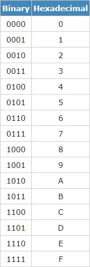
If you would rather enter the 8 values for each character into the LCD_Emojis.ino sketch as hexadecimal, here is a binary-to-hex converter to use. |
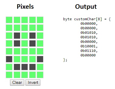 The Output is shown top down for each 5-bit row. Only the first 5 bits of an 8-bit binary number are used because each character row is only 5 pixels wide. A row with all of the bits selected: 11111 - Represented as a binary number: 0001 1111 - The first 3 bits ignored: 1 1111 - Formatted as a binary number: 0b11111 - Formatted as a hexadecimal number: 0x1F |
|
20x4_LCD_LineDrawing.ino
|
In the
sketch, 4 lines and 4 angles as custom
characters are used to create a box frame. Procedure 'displayBox()'
creates the outer box, and procedure 'displayHalfs()' writes in the
center of the screen to split the display into two boxes. The DHT11, DHT21 and DHT22 are relative cheap sensors for measuring temperature and humidity. Connection of the DHT11 sensor to Arduino is: '-' to ground, '+' to VCC, and 'S' (signal) to pin 5.
|
Video by
MechaTronics. 4X20 I2C LCD vendor 1, vendor 2. DHT11 Temp/Humid sensor vendor 1, vendor 2. Download this library from github and extract it. Under 'Arduino-master\libraries', you will see a folder named 'DHTlib'. Drag this folder to '..\My Documents\Arduino\libraries'.
|
20x4 LCD with I2C 'Backpack':
|
|
Adafruit RGB LCD Shield Library
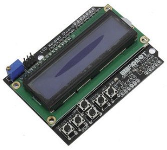
LCD_Shield_Parallel_Keypad.ino
|
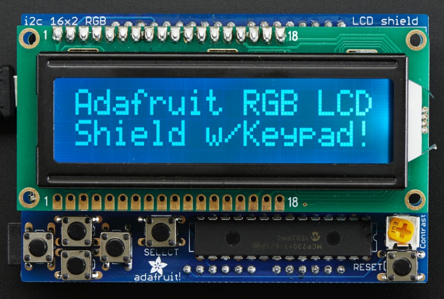
There are two devices with keypads shown
on the left (and on the right). The upper one is the I2C LCD from
Adafruit and the lower one is the parallel LCD from DFRobot. There are two separate sketches and libraries for each keypad equipped device. After downloading Adafruit's library, 'Adafruit-RGB-LCD-Shield-Library-master.zip'and expanding it, rename it to 'Adafruit-RGB-LCD-Shield' and drop it into your '..\My Documents\Arduino\libraries' folder. After downloading DFRobot's library, 'LCDKeypad_Library.zip'and expanding it, rename it to 'LCDKeypad' and drop it into your '..\My Documents\Arduino\libraries' folder.
|
Product Info: Vendor 1, Vendor 2. |
RGB I2C LCD Arduino Shield with Keypad
DFRobot Parallel LCD Arduino Shield with Keypad
|
|
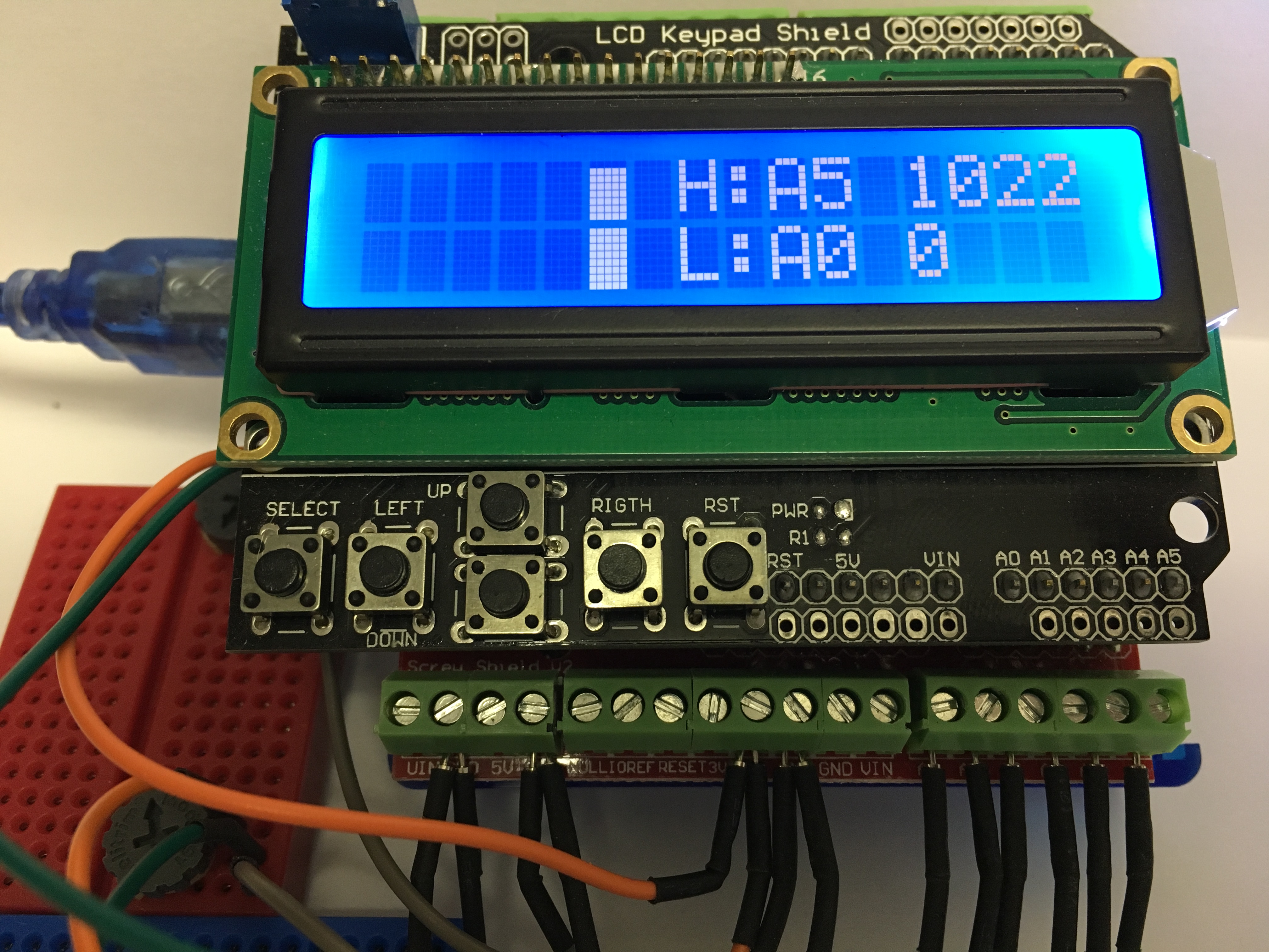
LCD_Shield_Parallel_Analog_Bar_Graph
|
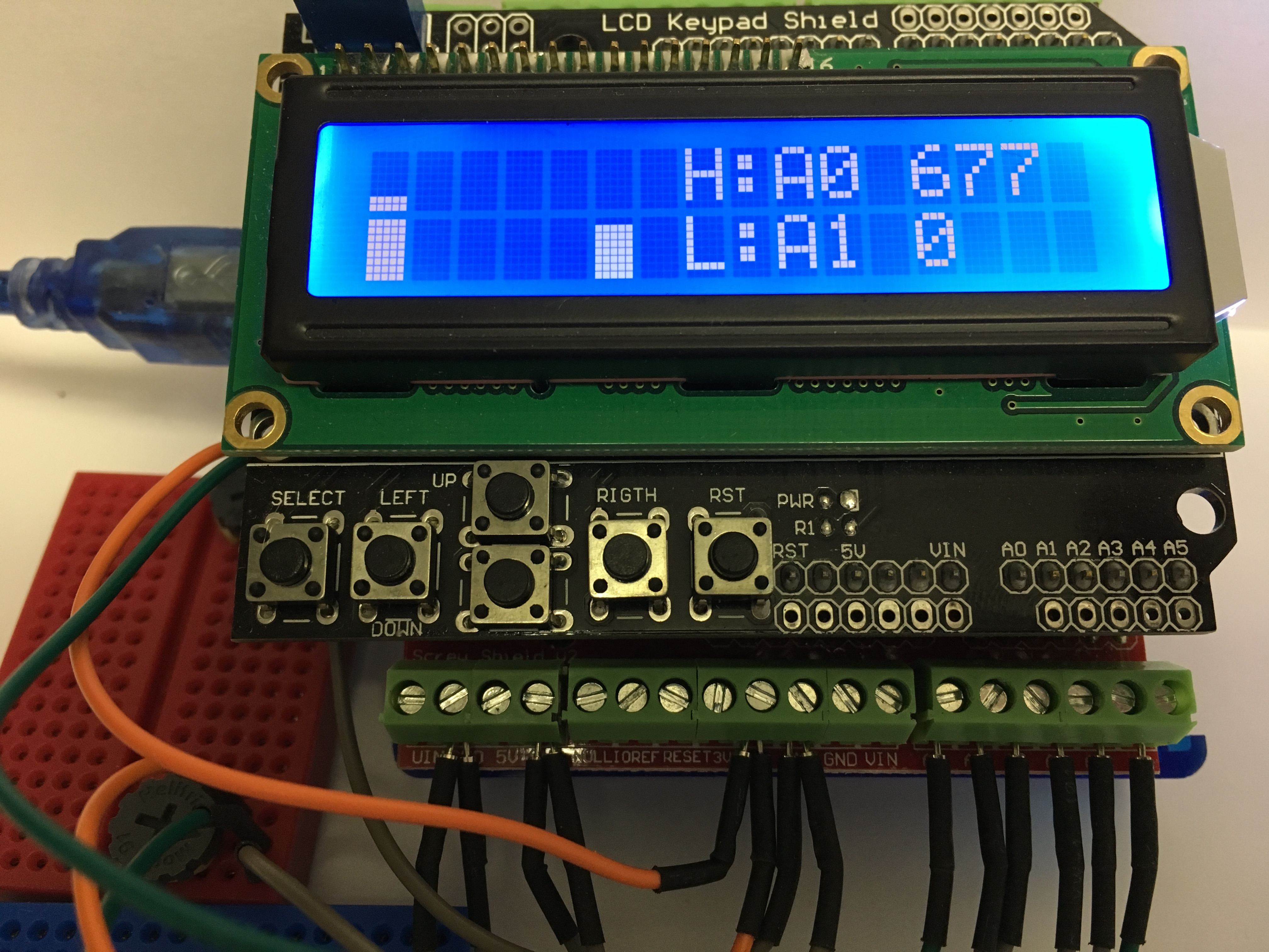
This sketch could display a bar graph of
the analog level for all 6 Analog (A0-A5) inputs. Only 2 (A0 and A5)
will be used in our demo. A4 and A5 are used for SDA and SCL respectively in I2C, so you'll need to use your parallel LCD for this sketch. Operation: A0 and A5 are attached to potentiometers. A1 through A4 are connected to Ground. A0 is adjusted to its lowest value (0v) and A5 is adjusted to its highest value (5v). The analog scale uses 0 for lowest and 1023 for highest. This scale is mapped to values between 1 and 16, with each row of pixels representing a mapped level (two vertical blocks = 2 x 8 rows). |
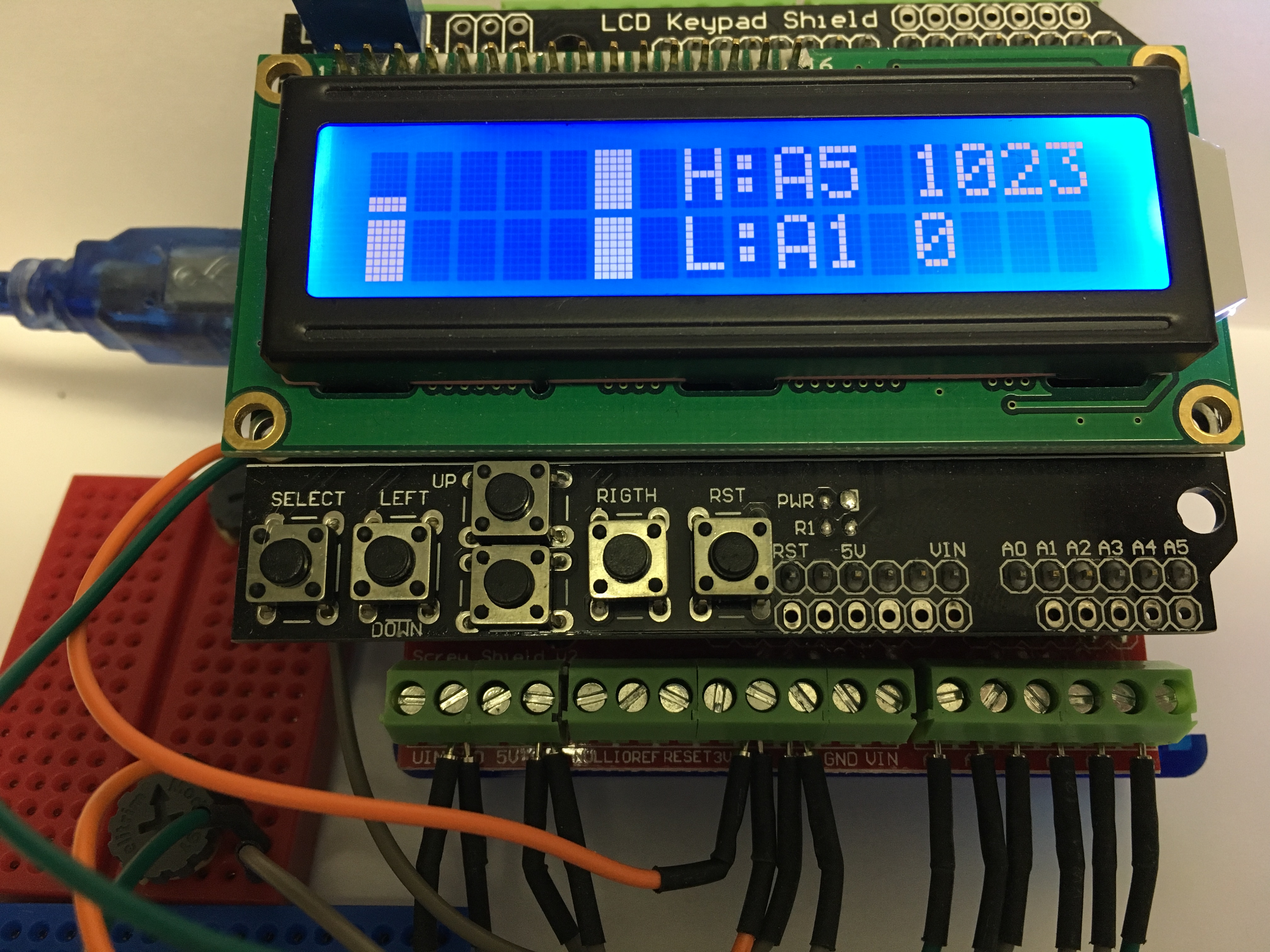
In the
1st .jpg, A0 is at 0 and A5 is at
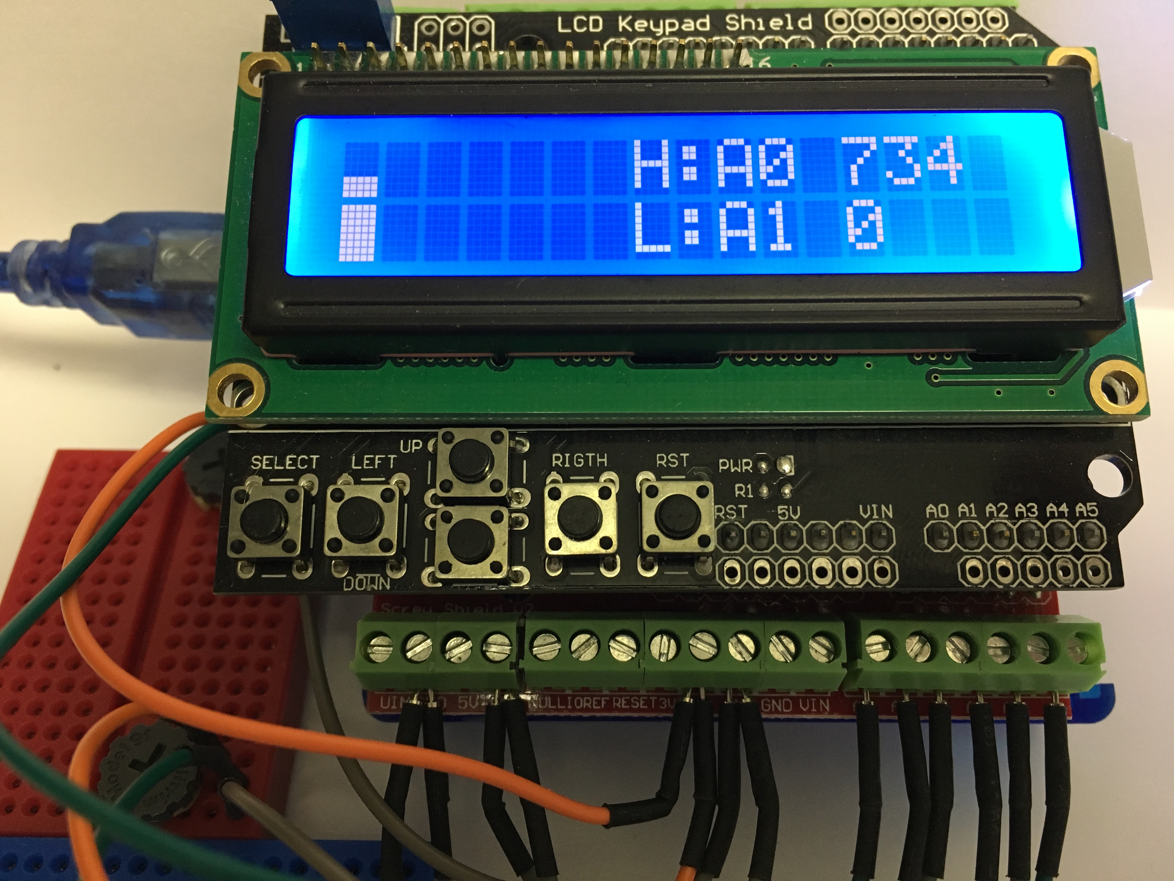
1023ish. Pot A0 is turned up to value 677 but this value is not yet seen because A5 has the highest value of 1023 and the "gauge" is designed to show highest and lowest values. Now that A0 is no longer at 0, A1 has the lowest value of 0; this is seen in the 2nd .jpg of the animated .gif file. A5 is lowered from 1023 to a value lower than A0 in the 3rd .jpg. This means A0 has the higher value of 677 and it is displayed. A5 is lowered further to 0 and A0 is raised slightly. In the 4th .jpg we can see A0 has the highest value of 734 and A1 has the lowest value of 0. In actuality, A1 through A5 are at 0 but the sketch chooses the left-most Analog port. Hackster.io project info. |
|
