| SKETCH NAME | DESCRIPTION & LEARNINGS | SOURCE LINKS | PROGRAMMING INFO |
|
|
Blink an LED programmatically. The built-in
LED on digital pin 13 is used. If you find that LED is too small
to see, you can add another 3mm or 5mm LED to pin 13. If you add an LED
to any other digital pin, you must use a current limiting resistor (220
ohm, 330 ohm, 470 ohm). This is usually your first Arduino sketch (program). Consider learning it well because you're going to use it at a later date for advanced subjects like multitasking. The 'void setup() {}' function runs once and the 'void loop() {}' function runs forever. Variables like 'LED_BUILTIN' can be placed in the 'setup' function. |
Info Link |
Variable name, LED_BUILTIN, is assigned the value, 13, automatically when used on an Arduino UNO. Other specialized Arduinos may use a different digital pin. 'pinMode' command configures digital pin 13 (D13) to be an output. 'digitalWrite' commands send a digital '0' or a digital '1'. 'digitalWrite(pin, HIGH)' commands are digital ones (1), and are measured at 5v on Arduino UNO or 3.3v on the new generation Arduinos. 'digitalWrite(pin,LOW)' commands are digital zeroes (0), and are measured at 0v on all Arduinos. In the Blink.ino program, the 'digitalWrite(13,HIGH)' command sends a digital '1' to pin D13, waits one second, then sends a digital '0' to D13 via 'digitalWrite(13,LOW)' command. This has the effect of turning the built-in LED on pin 13 on for one second (1000ms), then off for one second. Cumulatively, the LED "flashes" every 2 seconds. Change the 'delay()' interval to 100ms to see it actually flash much quicker. |
|
Fade.ino
|
Fades an LED on pin D9 using the 'analogWrite()' function. Teaches PWM range to illuminate or fade a LED. The 'if' statement is introduced.
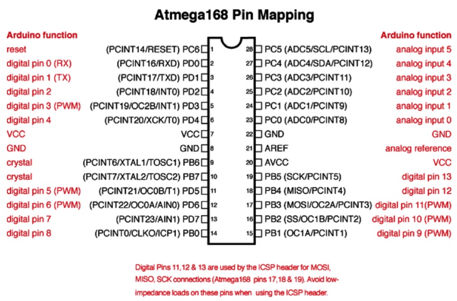
Pinout for Arduino UNO with ATmega328P chip:
|
Info Link |
Digital pins 3, 5, 6, 9, 10, 11 can perform pulse width modulation (PWM). PWM varies the signal duty cycle: the amount of 'on' time versus 'off' time for a fixed interval of time. PWM range is between 0 and 255; 0 is fully off, 127 is half-on, and 255 is fully on. If we start the PWM value at 0 and increment it to 255, we will see the LED increase in brightness. Reversing the PWM value from 255 to 0 will show the LED fading. 'digitalWrite' commands do not send analog-like PWM signals but 'analogWrite(pin,x)' commands do. You will need a current limiting resistor (220 ohm or 330 ohm or 470 ohm) in addition to a 3mm or 5mm LED. The Fade2.ino sketch uses the serial monitor to show the current brightness and fadeAmount values. |
|
LED_Bar_10a.ino
|
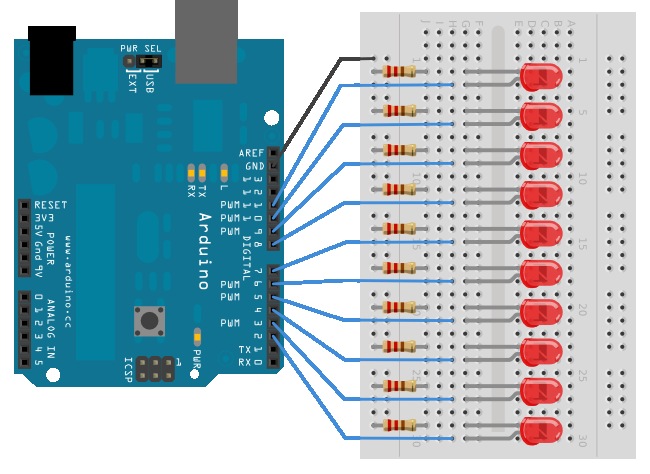
The sketch reinforces using six 'for' statements: - Two to illuminate the LEDs cumulatively from right to left, and then reverse direction. - Two to illuminate the outside LEDs cumulatively toward the center, and then reverse the direction. This is performed twice with the last two 'for' statements. |
Info Link |
The
schematic listed in the Description
file shows how to wire the circuit. Different
current limiting resistors can be used,
e.g., 220 ohm, 330 ohm, 390 ohm, 470 ohm, etc. I chose 390 ohm resistors
so the video would not be washed out from too much LED brightness. A prototyping shield was used with the Arduino UNO. It makes for a less cluttered development area. There are numerous shields available in the US and China. The .gif file on the left shows the operation speeded up for demonstration purposes. |
|
LED_Bar_Graph2.ino
|
Use the same circuit/schematic as shown above but with a potentiometer attached to analog pin, A0. The circuit uses a series of LEDs to display the input level of an analog sensor. Teaches how to use an array for quick pin assignment. Introduces the 'map' function that remaps a number from one range to another. A 'float' is introduced as a precision number in addition to 'int' integers. 'if else' loops are used to
set/reset LED states. |
Info Link 1 |
A parts list and schematic can be found at Info Link 2. Analog pins, A0 through A5, use a 10-bit analog-to-digital converter, ADC, to measure the signal voltage, using a scale of 0 to 1023. A potentiometer with 3 leads is attached to the circuit. One of the outside leads is attached to VCC, the other outside lead is attached to Ground, and the middle lead is attached to Arduino pin A0. Using the "pot" as a form of analog input to A0, we map the ADC scale (0 to 1023) to values between 0 and 10. With the pot set as low as possible to 0v, the value mapped will be 0. As we increase the voltage by 500mV increments, the first of ten LEDs (5.0v / 0.5v = 10) will be illuminated. Thus with 0v, no LEDs are lit. With 2.5v selected on the potentiometer by rotating the adjuster, 5 of 10 LEDs will be illuminated. And with 5.0v selected, all 10 LEDS will be lit. |