![]()
| Single-Step / Multi-Step Variable Speed CPU Clock Module | ||
|
Pix/Vids/Schematics (click to enlarge) |
Info |
|
|
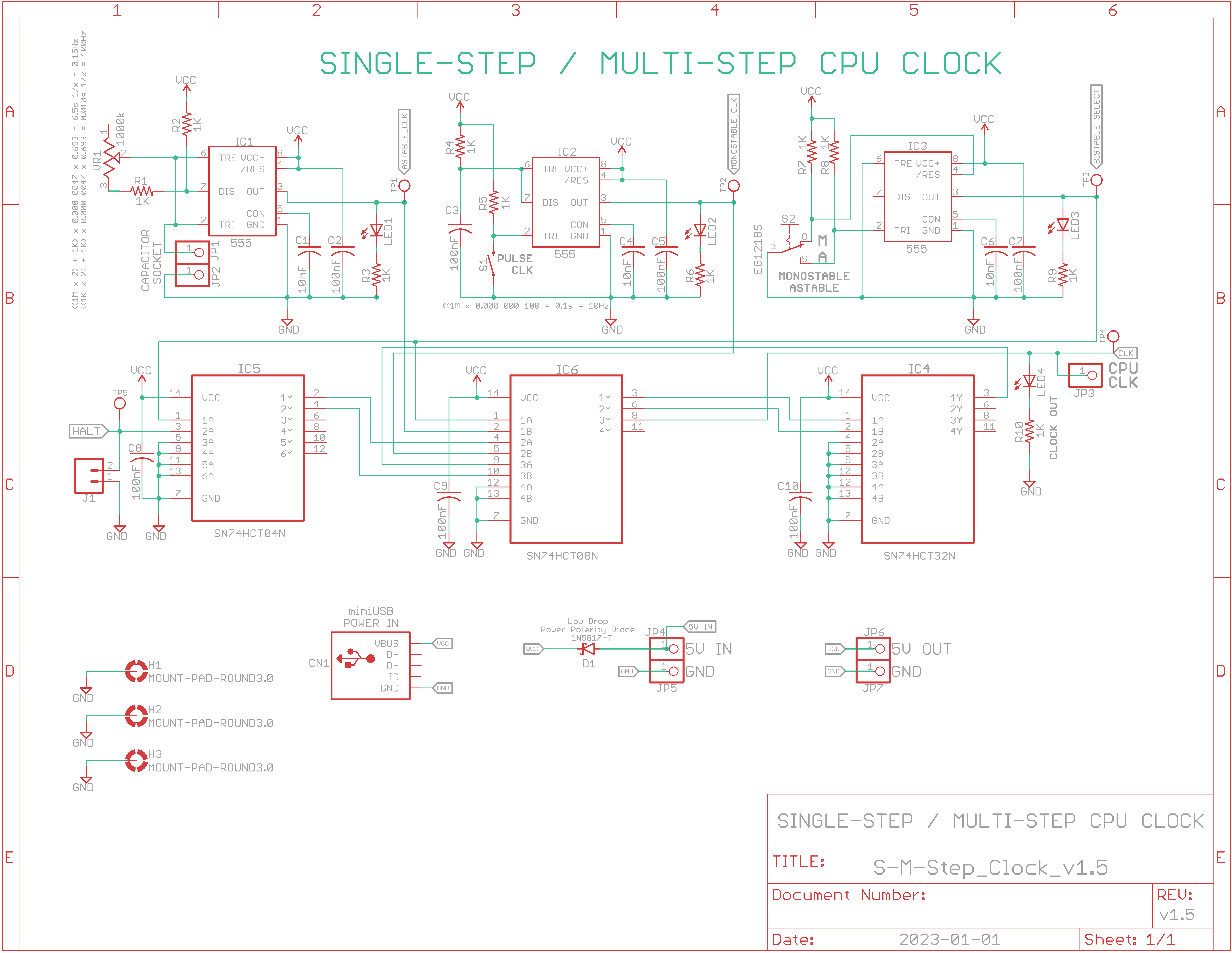
Eagle CAD: v1.5 Schematic
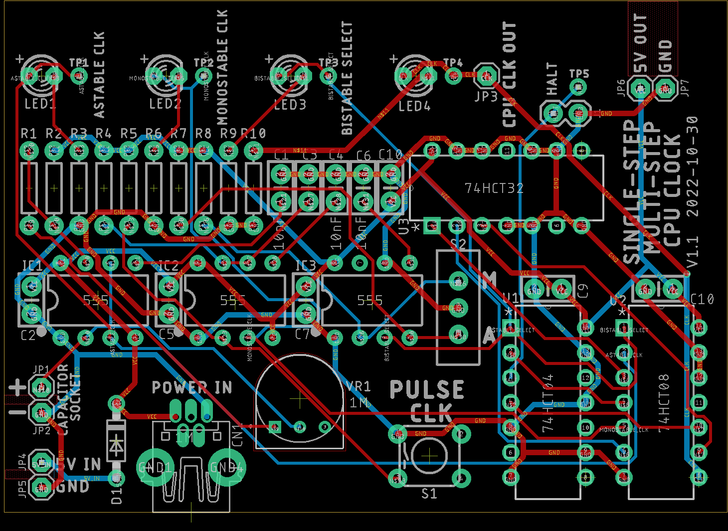
Eagle CAD: v1.5 Board Layout
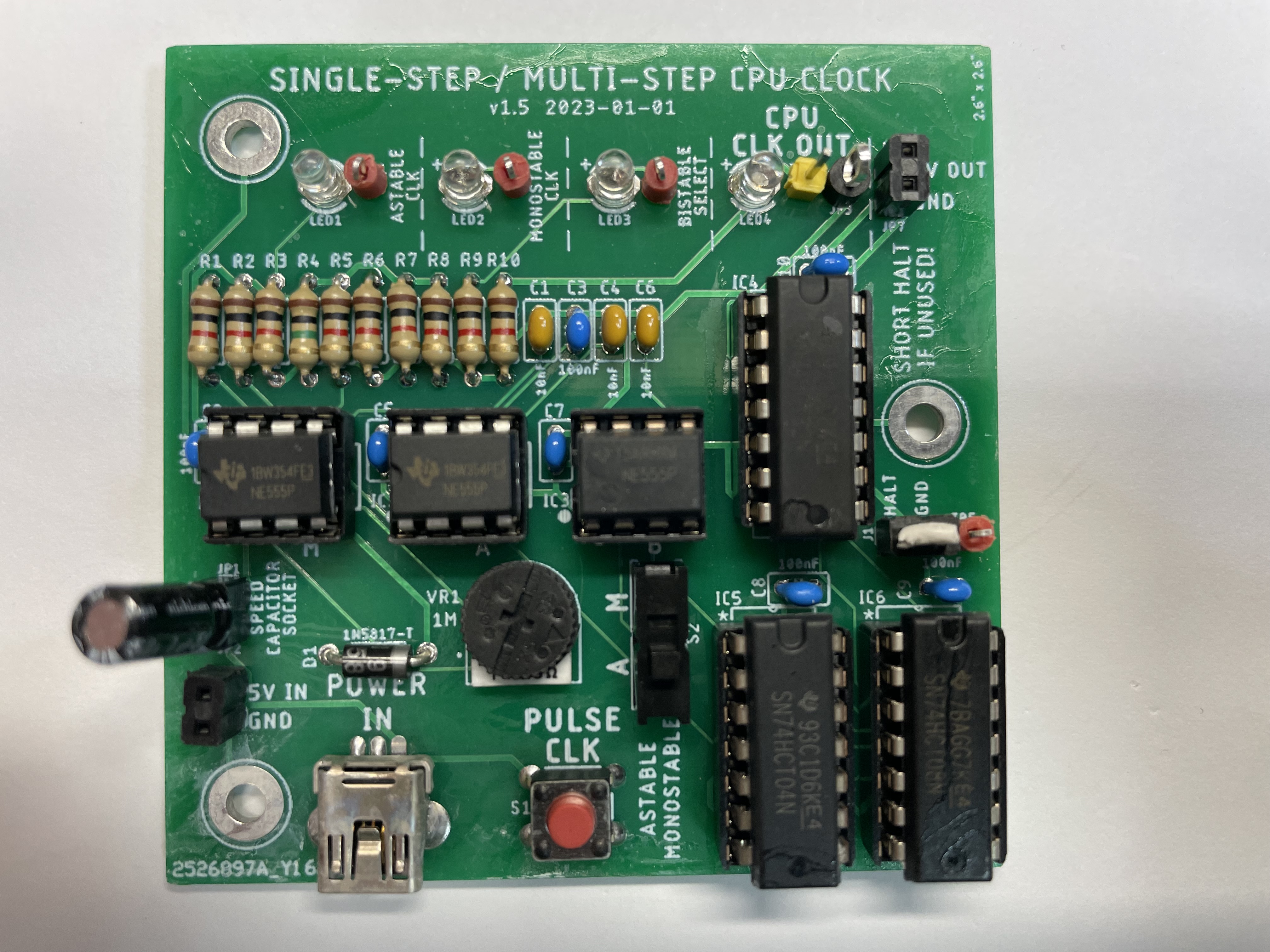
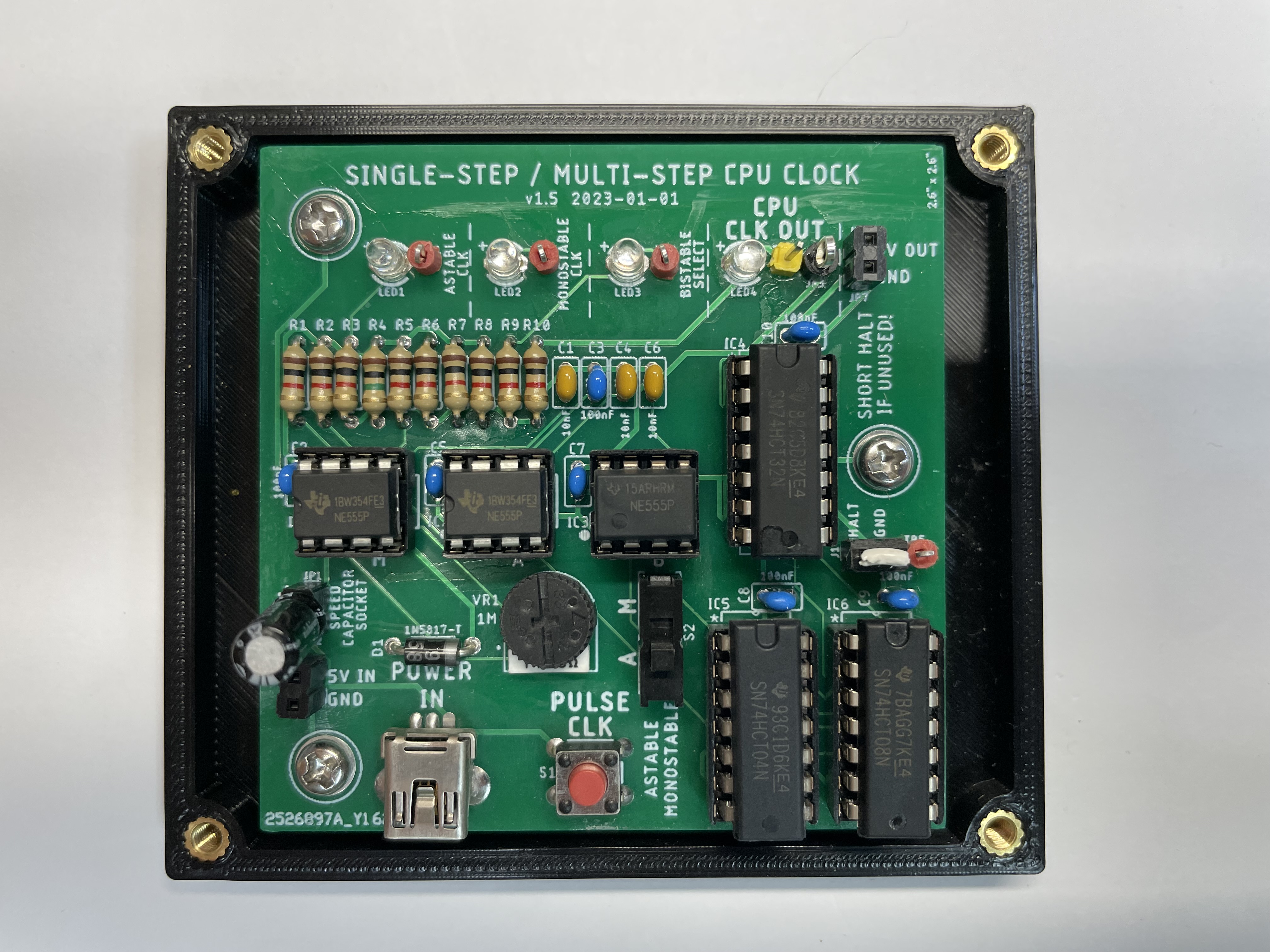
PCB: v1.5 Top
Eagle CAD:
v1.5 BOM
|
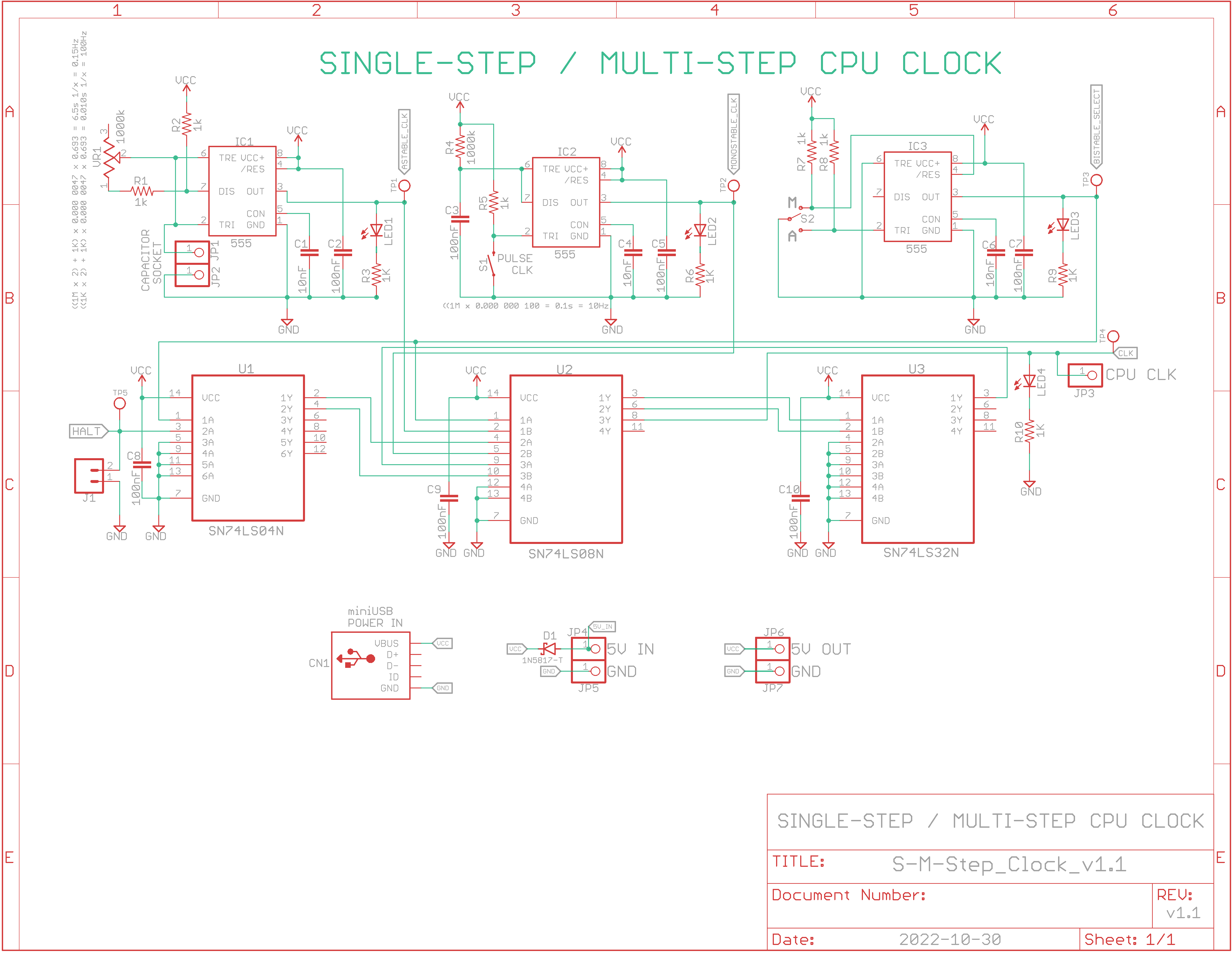
Eagle CAD: v1.1 Schematic
Eagle CAD: v1.1 Board Layout
PCB v1.1: Top
Eagle CAD: v1.1 BoM (Bill of Materials)
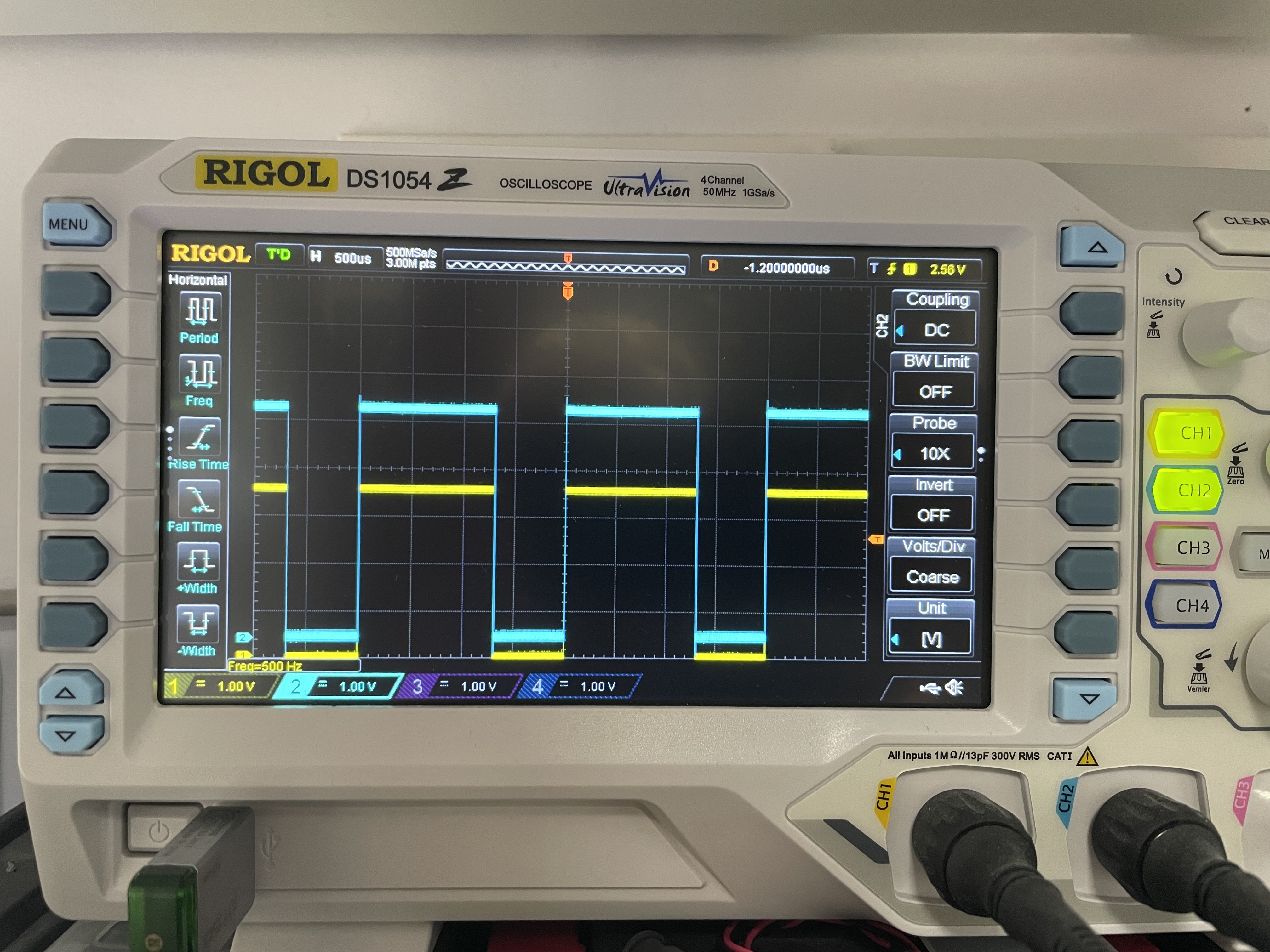
Scope Screenshot: 'clean' signal at 500Hz
Video: v1.5 Manual Operation & Automatic Operation: Adjust 1Hz to 500Hz
|
Description: This PCB is based on Ben Eater's CPU Clock module breadboard design. The latest PCB version is 1.5.
Features: - Astable and Monostable modes are selected via the A-M slide switch - In Monostable mode each press of the momentary push button will cause a square wave pulse - In Astable mode the clock runs freely from 1Hz to 500Hz via the trimpot position - The HALT input allows CPU to halt the clock output to the CPU. Remember to jumper this input or you'll experience erratic operation! - Test points and LEDs are available at: Astable, Monostable, Bistable Select, CPU Clock and Halt - 2-pin socket so you can switch out capacitors for more speed. I used 1uF electrolytic but have attained speeds of 250kHz with a 1nF ceramic cap.
Power Input: - Power is from a diode-protected 5v 2-wire connector or miniUSB connector
Video and Picture In the attached video, the potentiometer is adjusted so that the signal speed increases from less than 1Hz to 500Hz. You can see the scope screenshot showing a clean signal at 500Hz. The yellow scope signal was taken at TP1 which was the output of the Astable Clock. The blue signal was taken at TP4 after it had been conditioned to TTL levels via the 74HCT08.
The single-step function works via the momentary push button.
Don't forget to short the HALT jumper until you actually implement that function on your system or you'll notice odd behaviour of the output signal due to pin 3 of the 7404 left floating.
Using the miniUSB port to power the 6502 computer, the S-S/M-S Clock board, the breadboards with the ACIA and the Arduino Mega2560 clone, the total power consumption was about 180mA at 5.15v. |


Updated 2023-06-07 @ 8am
![]()