![]()
| Variable 1Hz-500Hz CPU Clock Module | |
|
Pix/Vids/Schematics (click to enlarge) |
Info |
|
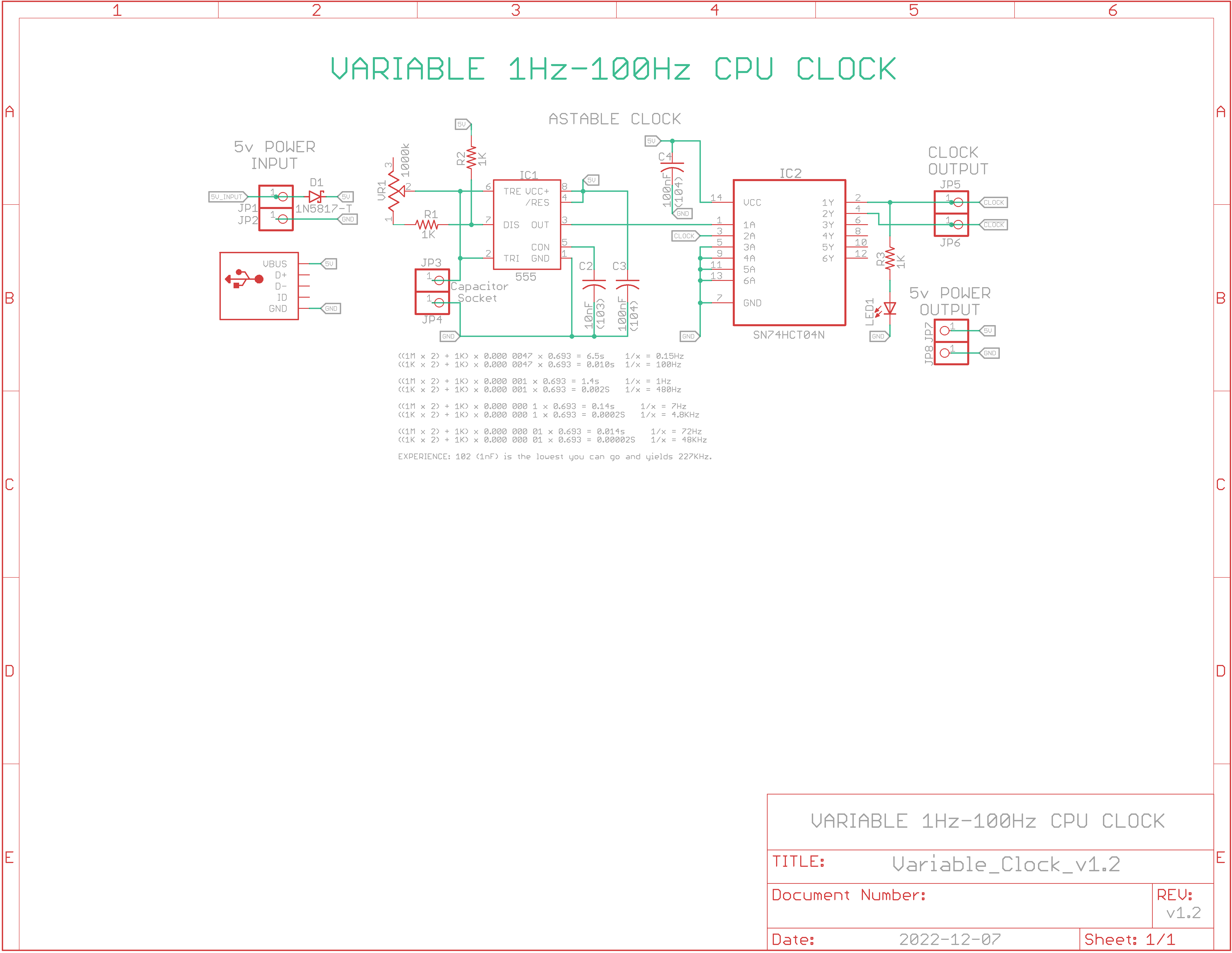
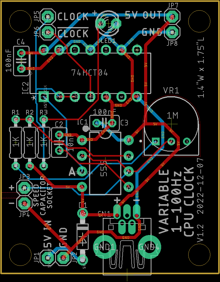
Eagle CAD: v1.2 Schematic Eagle CAD: v1.2 Board Layout
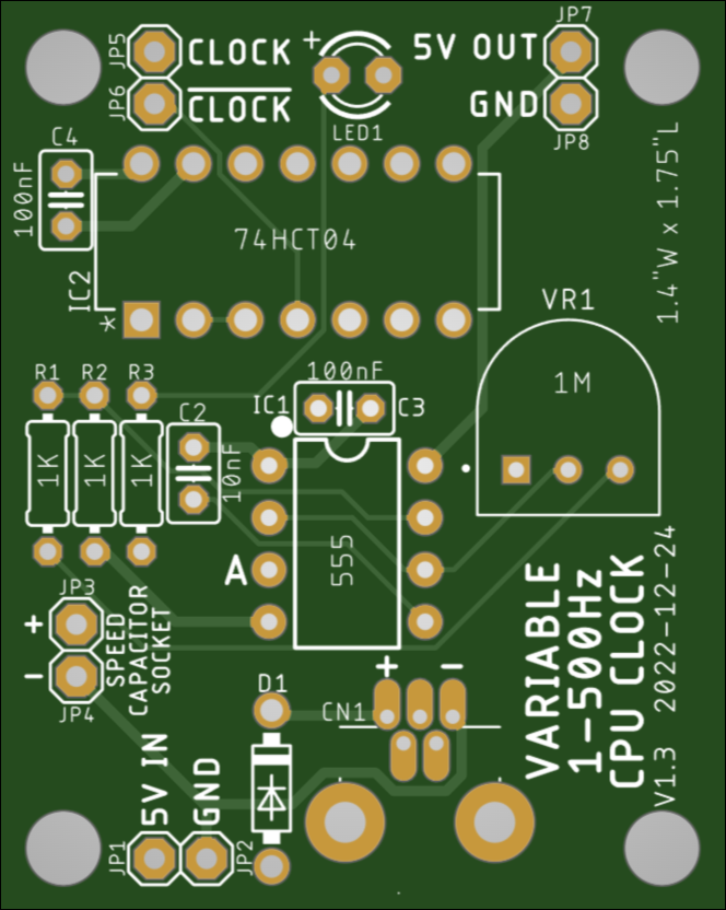
v1.2 PCB (Top)
v1.2 BoM (Bill of Materials) with Digikey Part Numbers
Short Video: Varying Speed from 1Hz to 500Hz
|
Description: This PCB is based on Ben Eater's CPU Clock module breadboard design but only the astable portion.
Features: - Output is 1Hz to 500Hz with a 1uF electrolytic capacitor (227kHz with a 1nF cap) - Synchronized LED flashes are via the CLOCK or CLOCK output connectors - 2-pin socket so you can switch out capacitors to smaller values for more speed - 5v output connector was added in v1.2 to also power the device under test - Two grounded 3mm (0.12") mounting holes
Power Input: - Power In is from a diode-protected 5v 2-wire connector or miniUSB but not both
|

Updated 2022-12-24 @ 8am
![]()