![]()
|
ItsyBitsy M4 Express Projects 24 & 25: 9 DoF IMU or Accelerometer |
||
|
Pix/Vids/Schematics (click to enlarge) |
Info | |
|
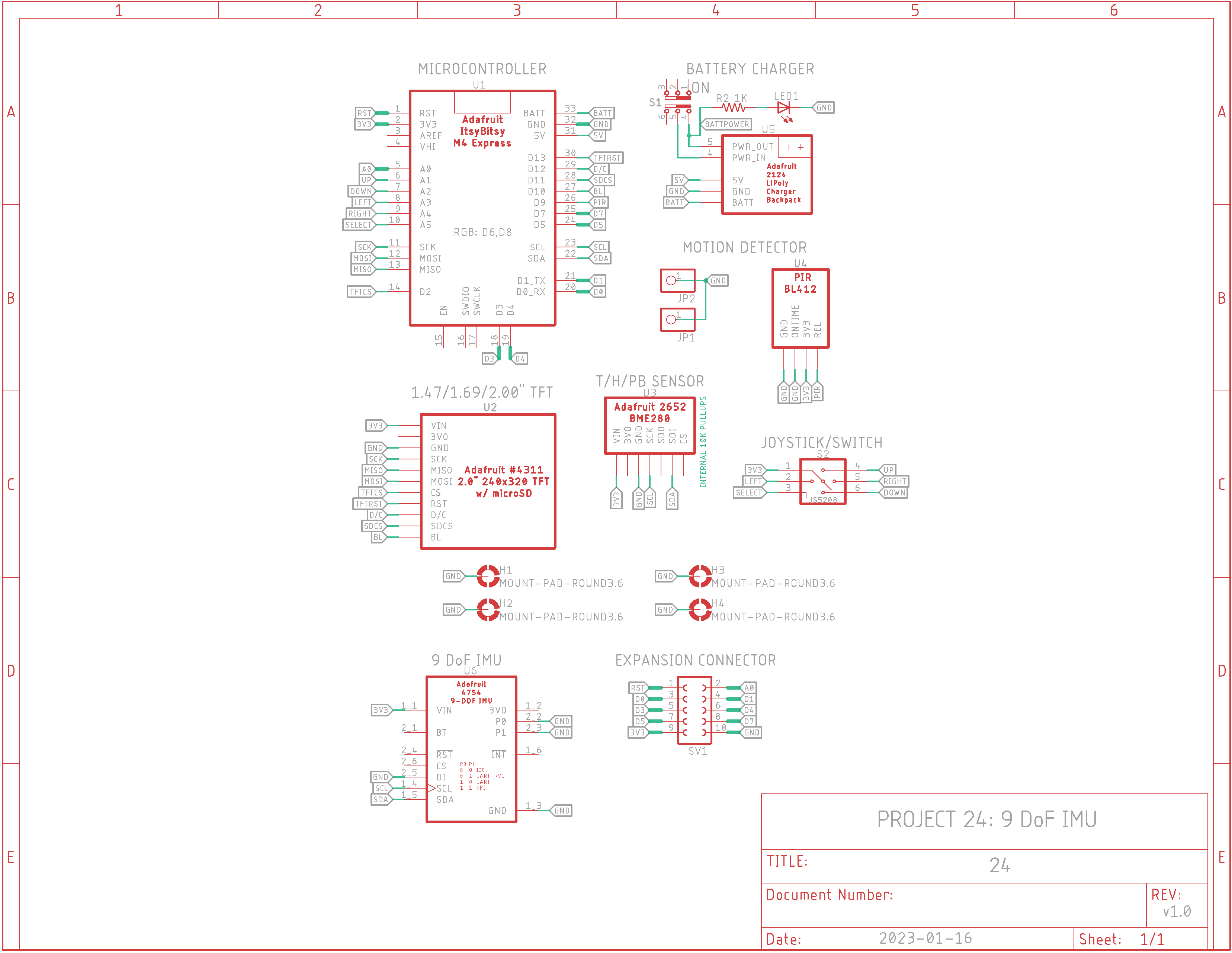
9 DoF IMU v1.0 Schematic
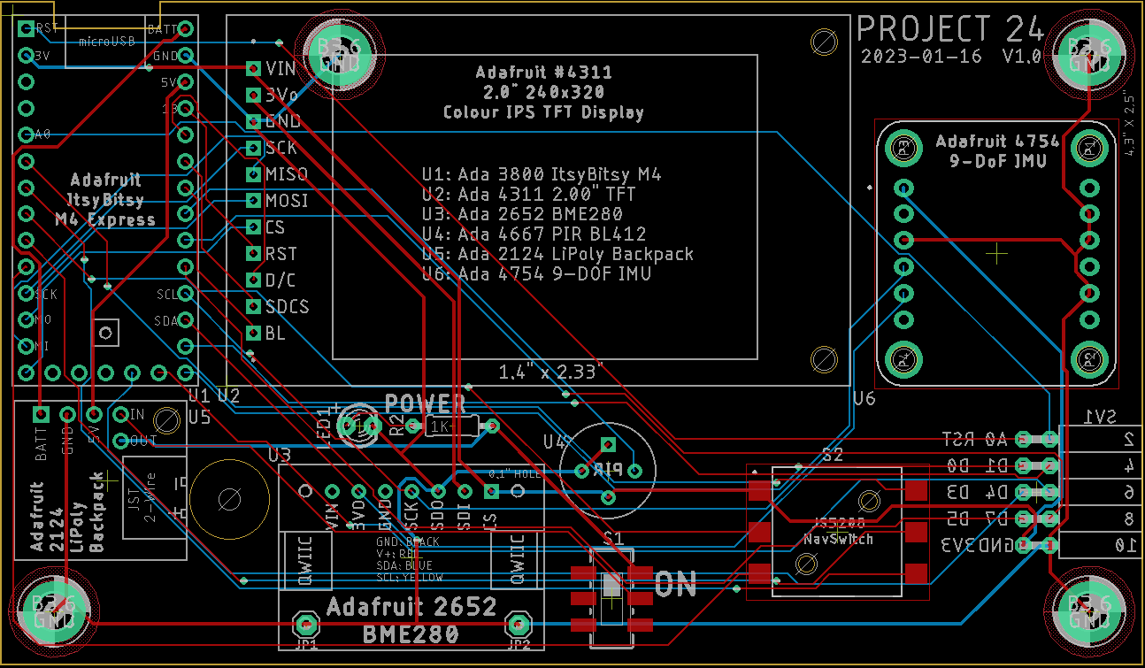
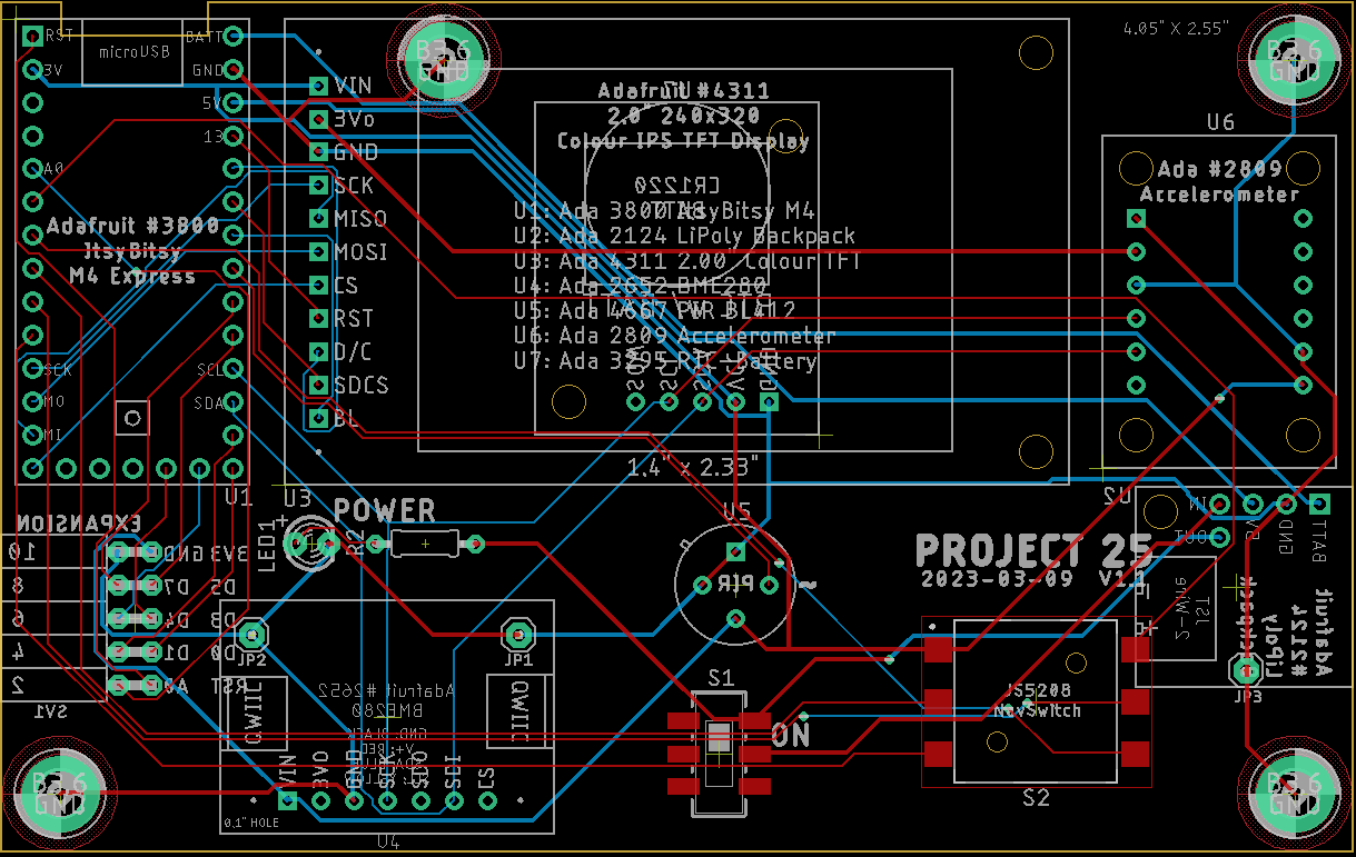
9 DoF IMU v1.0 PCB Layout
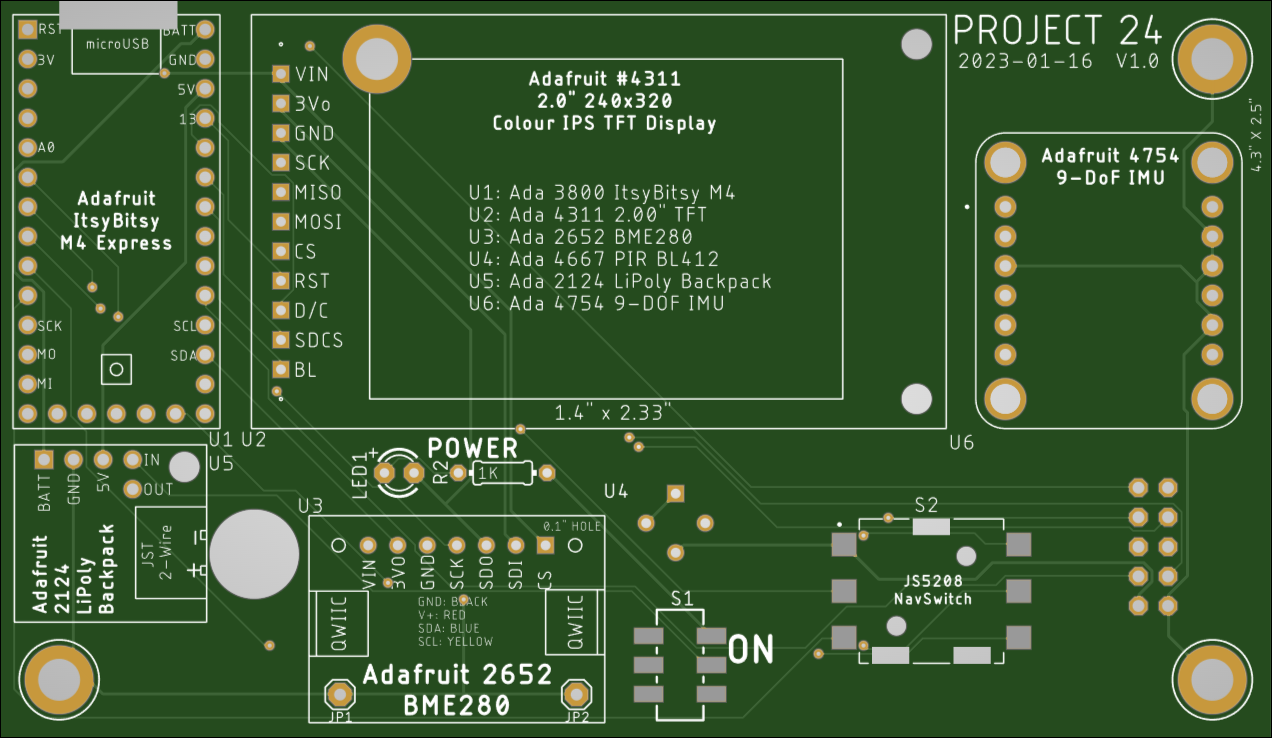
9 DoF IMU v1.0 PCB (Top)
9 DoF IMU v1.0 PCB (Bottom)
9 DoF IMU v1.0 Bill of Materials
|
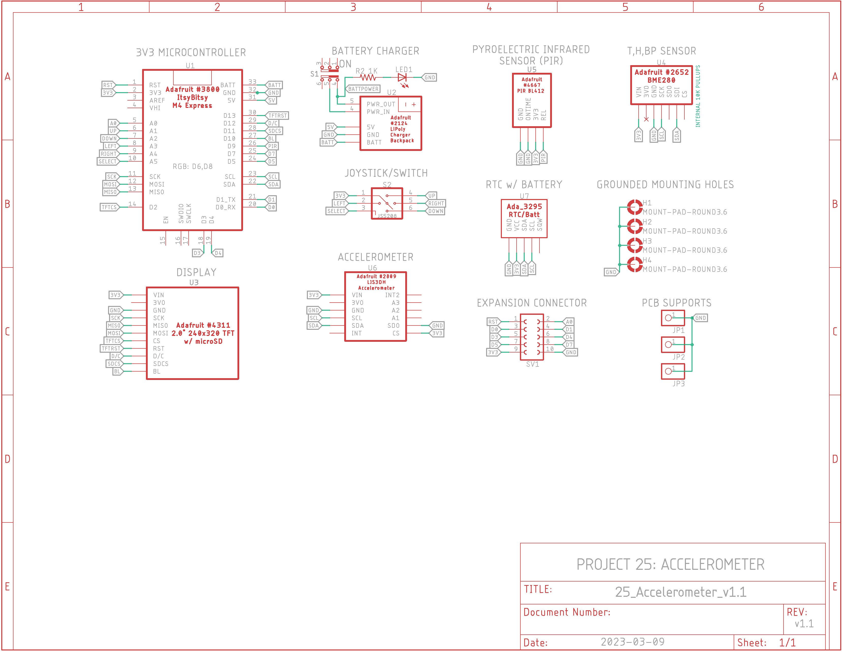
Accelerometer v1.1 Schematic
Accelerometer v1.1 Board Layout
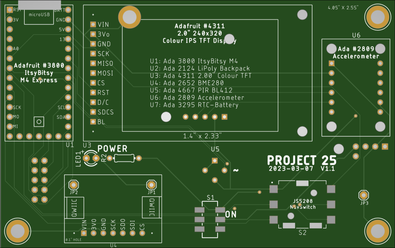
Accelerometer v1.1 PCB (Top)
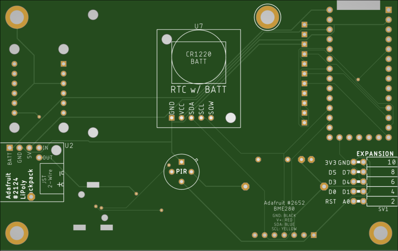
Accelerometer v1.1 PCB (Bottom)
Accelerometer v1.1 Bill of Materials
|
Description: Projects 24 & 25 continue on from Project 23 using these devices: - Adafruit ItsyBitsy M4 Express #3800 (a.k.a. IB-M4E) (more I/O pins than QT PY) - Adafruit #4311 2.0" TFT display - Adafruit #2652 BME280 T/H/BP sensor - Adafruit #2124 LiPoly charger - Joystick JS5208 and Adafruit #4697 rubber nub cap - Adafruit #4667 PIR BL412
For each project a sensor board was added as shown below: Project 24: Adafruit #4754 9 Degrees of Freedom Orientation IMU Project 25: Adafruit #2809 LIS3DH Accelerometer
Testing Your Accelerometer or 9DoF: Make sure you install the appropriate libraries before testing the code below. You'll need to click on these #4754 and #2809 links for instructions. When you initially receive your your Accelerometer, test it with acceldemo_IBM4E.ino Test your 9 DoF with 9DoF-IMU_rotation_vector.ino first before adding it to the PCB.
Setting Up Your System: - Download and follow this .pdf file to setup the ItsyBitsy M4 Express microcontroller for Arduino: https://cdn-learn.adafruit.com/downloads/pdf/introducing-adafruit-itsybitsy-m4.pdf. Follow the directions regarding the .uf2 file because it is needed for either Arduino or CircuitPython programming. Search Adafruit.com for info on "flash_nuke.uf2" to cleanup your board if double-pressing the Reset button won't fix it. Check here first: https://learn.adafruit.com/getting-started-with-raspberry-pi-pico-circuitpython/circuitpython - Download and follow this .pdf file to setup the 2.0" 320x240 TFT display for Arduino: https://cdn-learn.adafruit.com/downloads/pdf/2-0-inch-320-x-240-color-ips-tft-display.pdf - Download and follow this .pdf file to setup the BME280 or BMP280 sensors: https://cdn-learn.adafruit.com/downloads/pdf/adafruit-bme280-humidity-barometric-pressure-temperature-sensor-breakout.pdf. Adafruit's new driver requirements seem to ward off the Chinese clones of their sensors, that is, what once worked no longer does. The Adafruit board is $15us so I'll continue to use their product.
Software: Here's some code that is a work in progress as I add more of the PCB devices to the board. The temp/BP sensor, RTC and Accelerometer are started up (which includes a quick test of each). Text is displayed on a non-black background, a different colour for each reporting line, e.g. date & time are black text on a white background.
|

![]()
Updated 2023-03-09 @ 8am
