![]()
|
Testing Your Microcontroller Board with CircuitPython, a BME280 Sensor and a Display |
||
|
Installation or operation problems? - Hit <Reset> button: Python disk drive boots up as RPI-RP2 - Drag flash-nuke.uf2 to RPI-RP2. Hold down <Boot> button, press & release <Reset> button, release <Boot> button. Board is now "scrubbed" if it boots showing drive volume name other than CircuitPy. Note: if you are having trouble with a non-RP2040 board like PyGamer or whatever, double-click <Reset> to enter boot mode then type the following in the REPL to clear the board: >>> import storage >>> storage.erase_filesystem() More info can be found here https://learn.adafruit.com/adafruit-pygamer/troubleshooting under Safe Mode. |
||
|
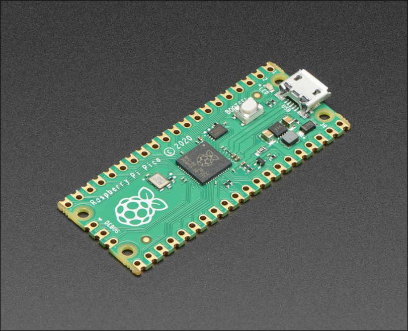
RPi RP2040 Pico
microcontroller board
|
Installation and startup: - Drag latest Adafruit CircuitPython .uf2 board file for the Pico to the RPI-RP2 drive and wait for it to reboot. Python drive now boots up as CIRCUITPY - a CircuitPython drive! - If the board reboots with the flash-nuke.uf2 file still intact, delete it - On CIRCUITPY drive, change to "lib" folder - Download the latest v7.x bundle, navigate to the "lib" folder and drag the "adafruit_bme280" library folder to the CIRCUITPY drive's "lib" folder - Hit <Reset> button: system will reboot as a CircuitPython system with a Temp/Humidity/BP sensor library installed - Copy the "bme280_simpletest_pico.py" file from the latest v7.x bundle "examples" folder to the root folder of the CIRCUITPY drive and rename it to "code.py". (Note how line 10 differs from the QT-PY version: "i2c = busio.I2C(board.GP17, board.GP16) # SCL, SDA") - Startup MU editor. Close any open files on your MU desktop. "Load" the code.py file you saved to the CIRCUITPY drive. Click the "Serial" button and the program should be running showing the current sensor data. If not, hit the <Reset> button. Because the file is named "code.py", it will run whenever the system is rebooted. |
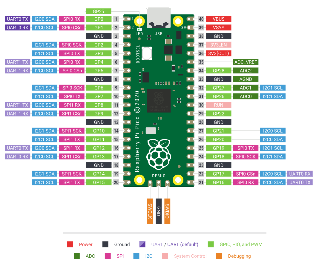
RPi RP2040 Pico Pinout
|
|
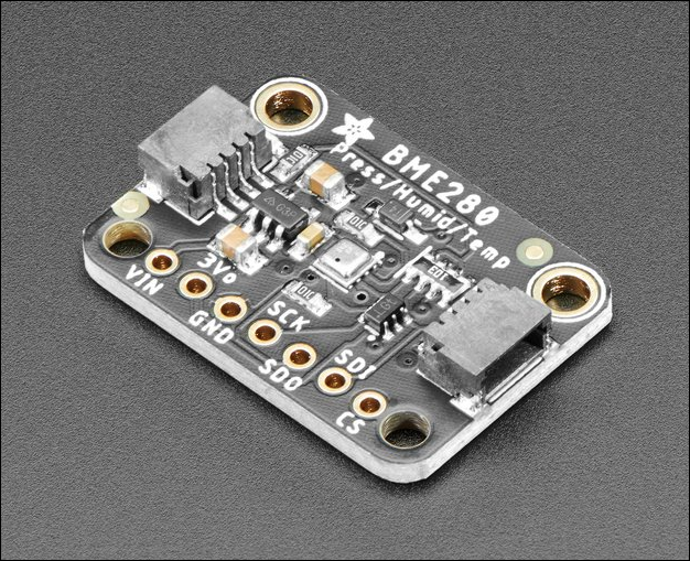
Adafruit BME280 Sensor NEW
|
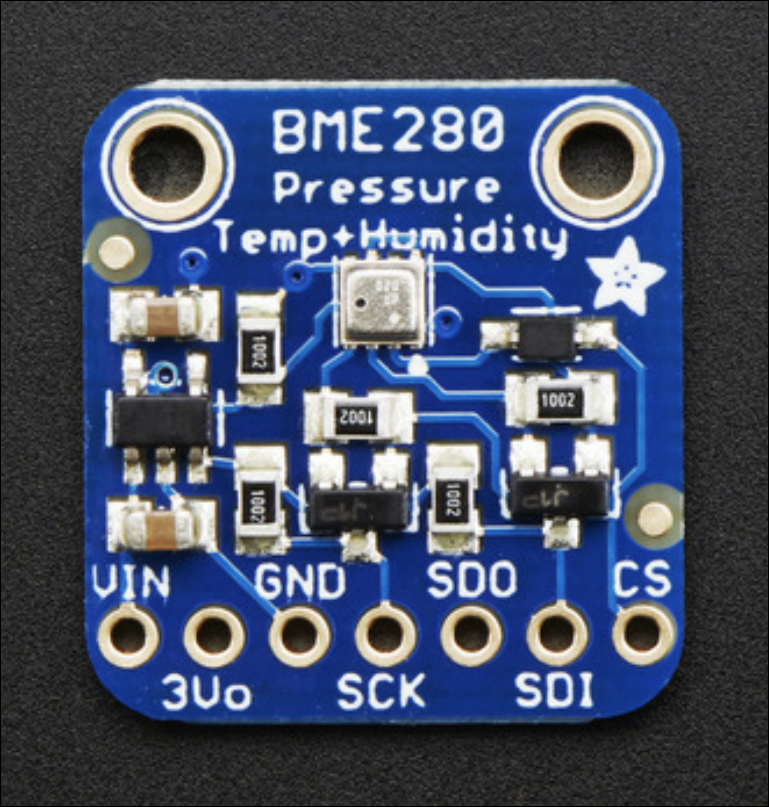
Adafruit BME280 sensor: - Temperature, Humidity, Barometric Pressure sensor - Supports I2C or SPI connection - 3.3v or 5v operation (onboard level-shifter) - Stemma QT connector for quick I2C hookup - Product guide available in .pdf format |
OLD BME280
|
|
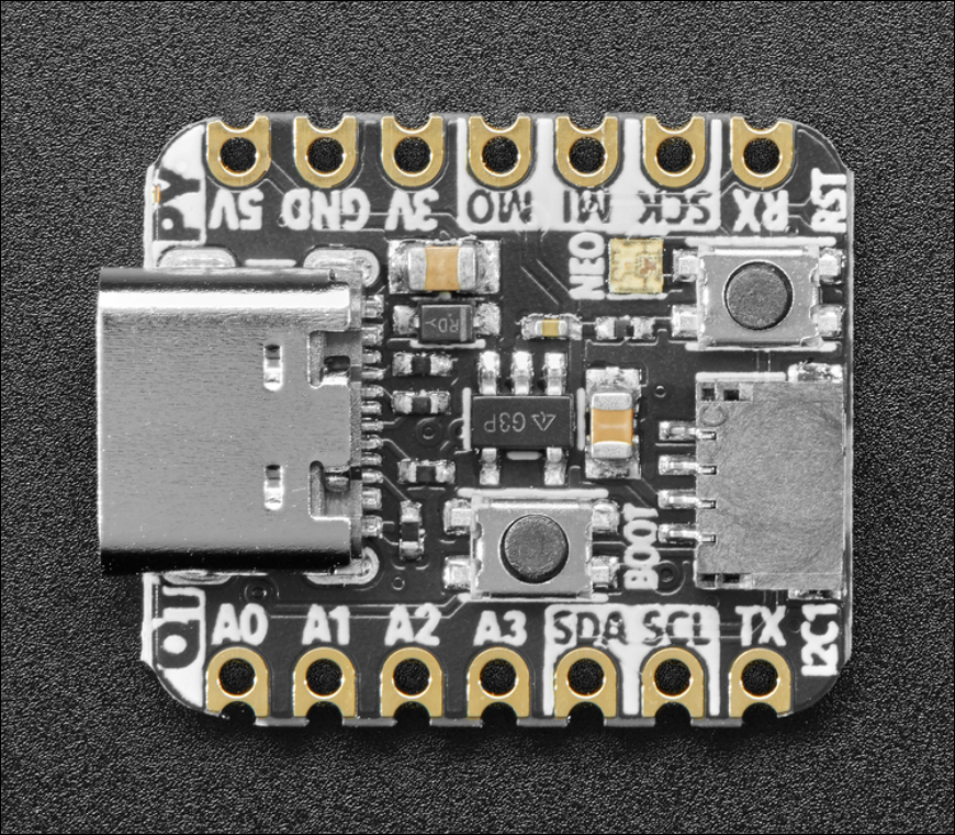
Adafruit QT-PY RP2040
microcontroller board
|
Installation and startup: - Drag latest Adafruit QT-PY2040 board .uf2 file to RPI-RP2 and wait for it to reboot. Python drive now boots up as CIRCUITPY - a CircuitPython drive! - If the board reboots with the flash-nuke.uf2 file still intact, delete it - On CIRCUITPY drive, change to "lib" folder - Download the latest v7.x bundle, navigate to the "lib" folder and drag the "adafruit_bme280" library folder to the CIRCUITPY drive's "lib" folder - Hit <Reset> button: system will reboot as a CircuitPython system with a Temp/Humidity/BP sensor library installed - Copy the "bme280_simpletest.py" file from the latest v7.x bundle "examples" folder to the root folder of the CIRCUITPY drive and rename it to "code.py" - Startup MU editor. Close any open files on your MU desktop. "Load" the code.py file you saved to the CIRCUITPY drive. Click the "Serial" button and the program should be running showing the current sensor data. If not, hit the <Reset> button. Because the file is named "code.py", it will run whenever the system is rebooted. |
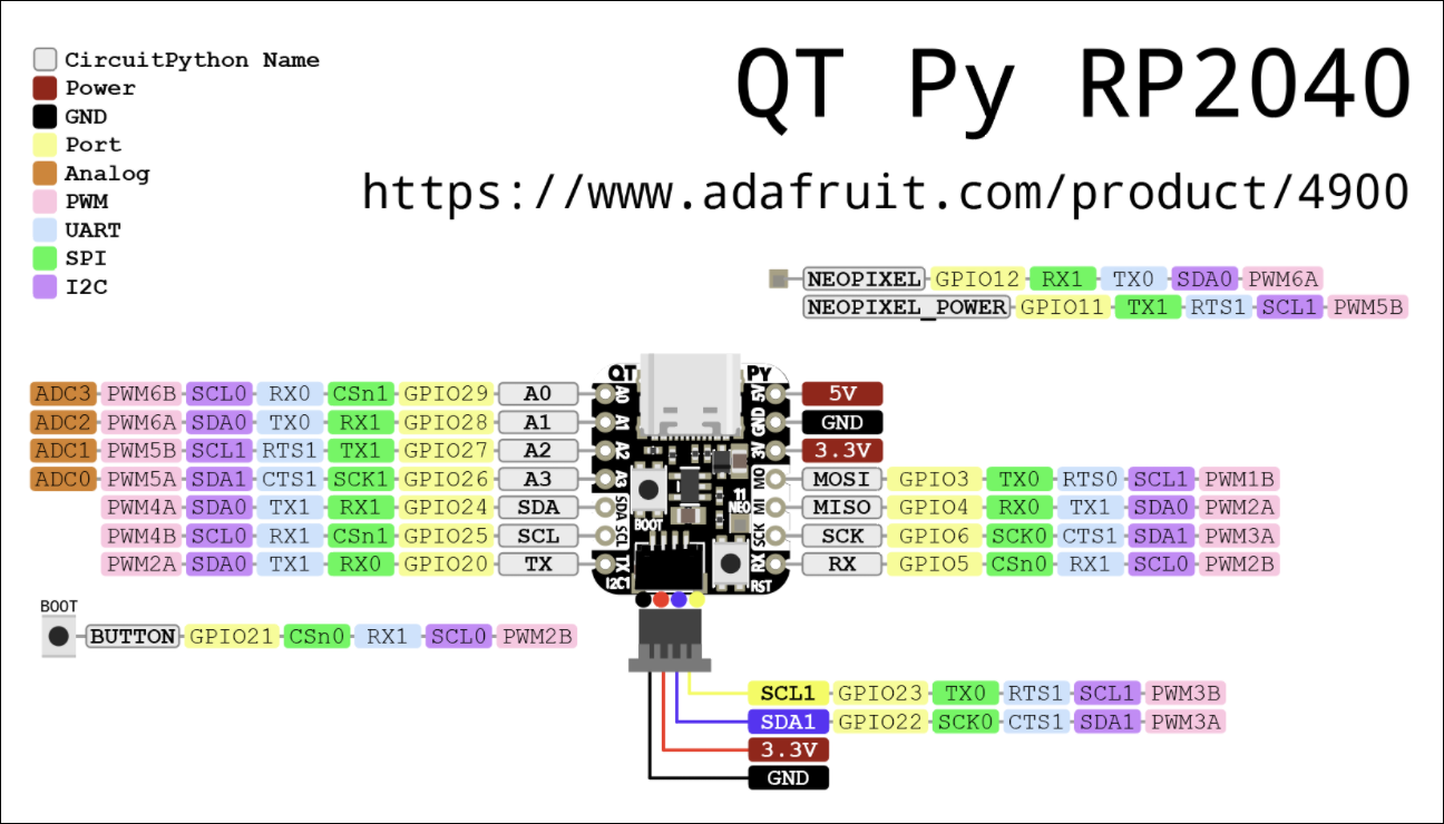
Adafruit QT-PY RP2040 Pinout
|
|
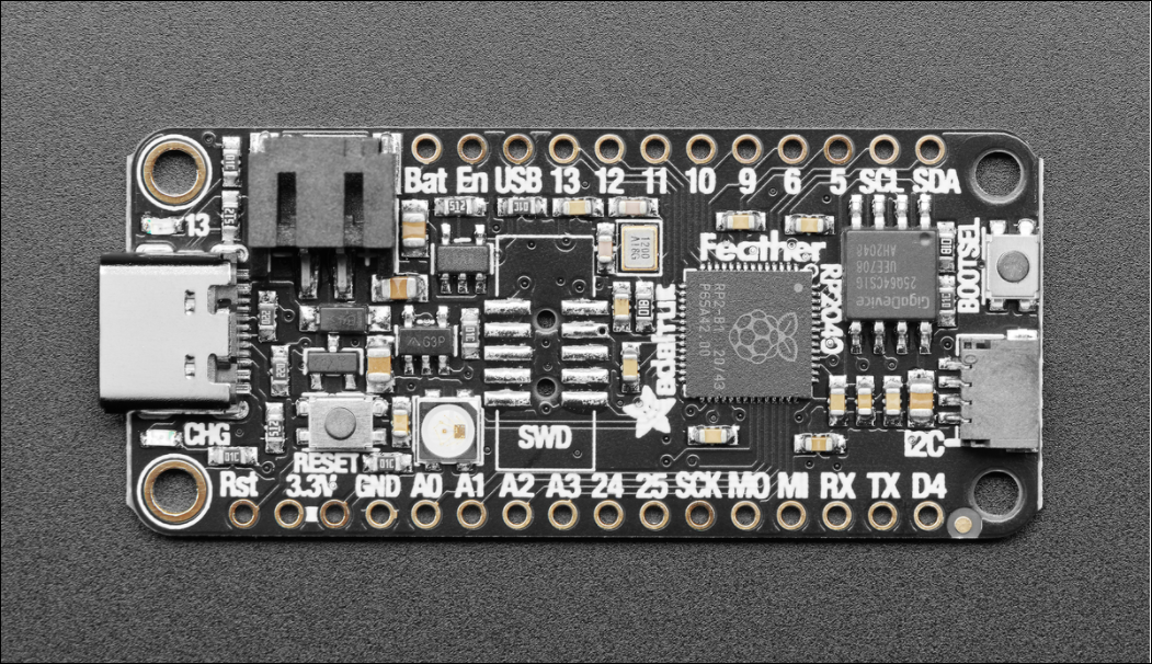
Adafruit Feather RP2040 microcontroller board
|
Adafruit Feather RP2040 The board utilizes common "Arduino pinout" arrangement for compatibility with all other Feather products It contains a full set of features like the RPi RP2040 Pico plus additional ones like: - 8MB QSPI Flash chip for storing files including Python files (microPython or circuitPython) - 2-pin JST PH connector for LiPo battery, includes 200mA charger and charging LED - USB-C connector for power or configuration - Separate BootSelect and Reset buttons: hold both then release Reset to bootload - StemmaQT/Qwiic/Grove connector for I2C peripherals - 3 LEDs: RGB neopixel, traditional red LED on pin 13, LiPoly charging/charged LED - CircuitPython v7.x for this board can be found here.
|
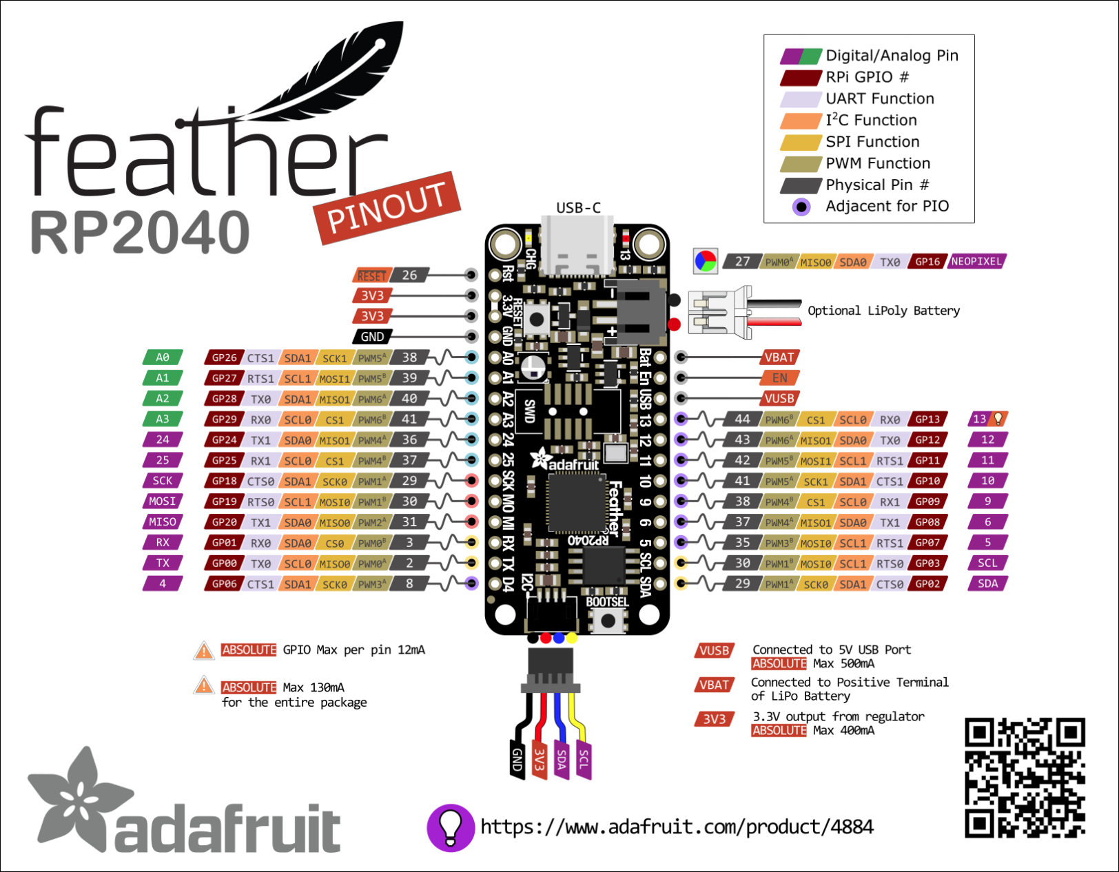
Feather RP2040 Pinout
|
|
Adafruit 3.5" TFT FeatherWing
Adafruit 2.4" TFT FeatherWing
|
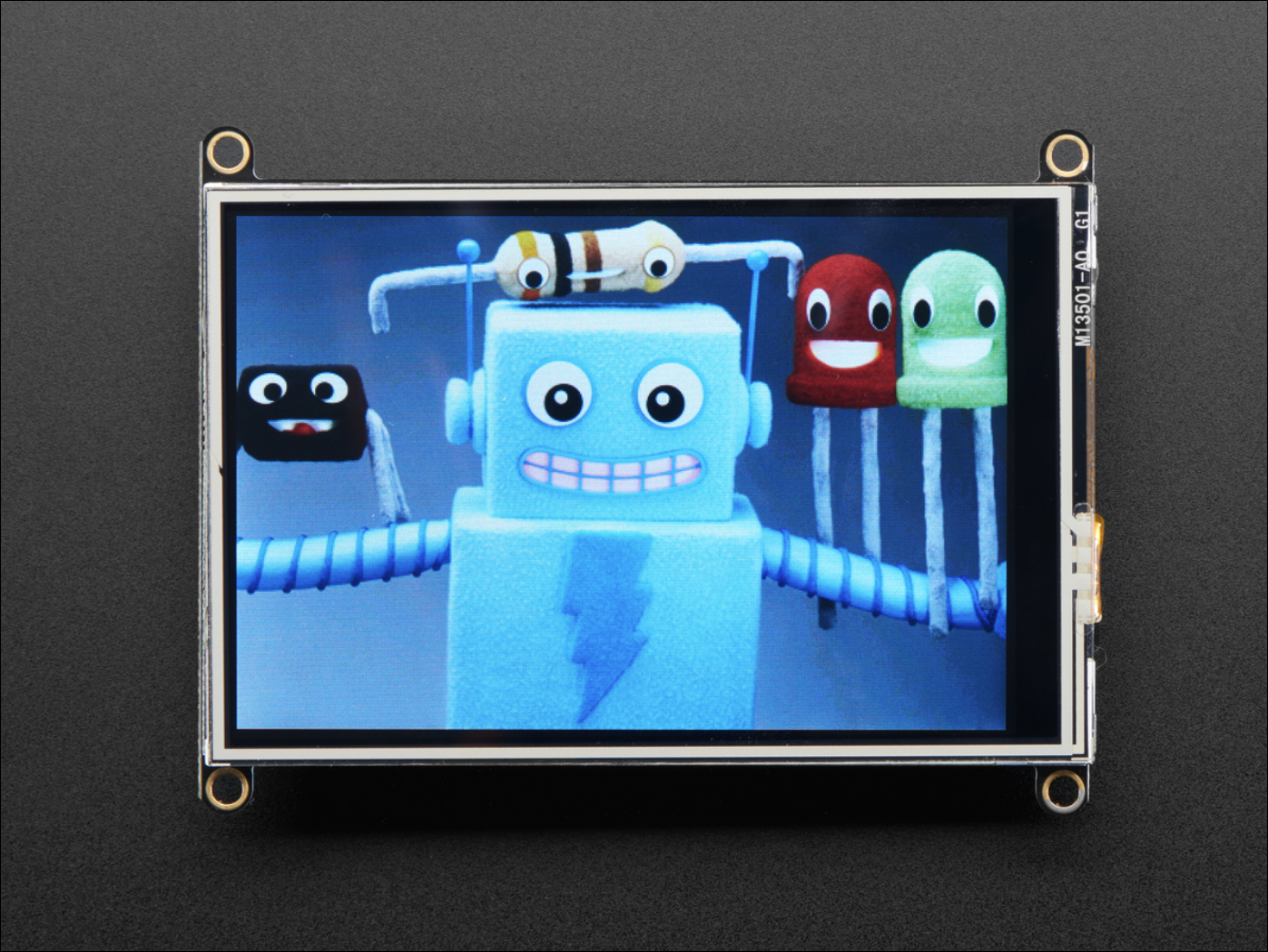
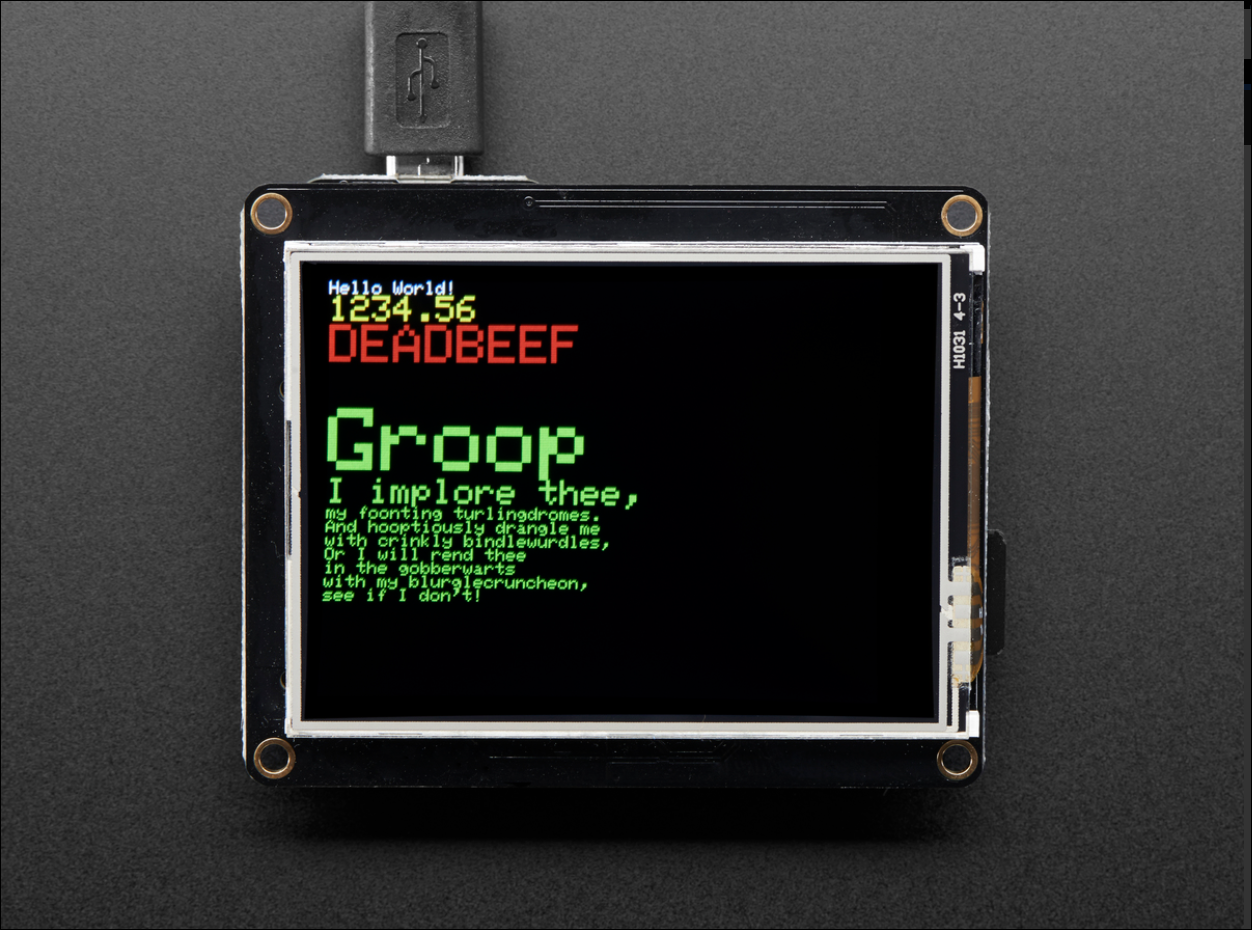
Adafruit 3.5" TFT FeatherWing TFT display with microSD storage for image files. - Resolution: 480 x 320 pixels - HX8357 display driver - Product ID 3651
Adafruit 2.4" TFT FeatherWing - Smaller TFT display with microSD storage for image files - Resolution: 320 x 240 pixels - ILI9341 display driver - Product ID 3315
Familiarization: To become familiar with pins, power and programming either of the displays listed above, the recommended document review order is: - 3.5" TFT FeatherWing or 2.4" TFT FeatherWing - CircuitPython displayio setup for TFT FeatherWings. Stop after you have read either the 3.5" or 2.4" sections - displayio Library Overview. This intro can be very helpful in learning how to display content - CircuitPython Display Text library. - displayio API Documentation which is "The" reference doc
Learn CircuitPython Programming: - Here are 10 free videos to get you started
|
displayio Hierarchy
Hierarchy & Nesting
Groups
|
| Adafruit Feather M4 Express |
Another handy reference: - GFX Graphics Library for Arduino (not CircuitPython) |
|
![]()
![]()