![]()
|
Part 5: VIA and UART Testing |
||
|
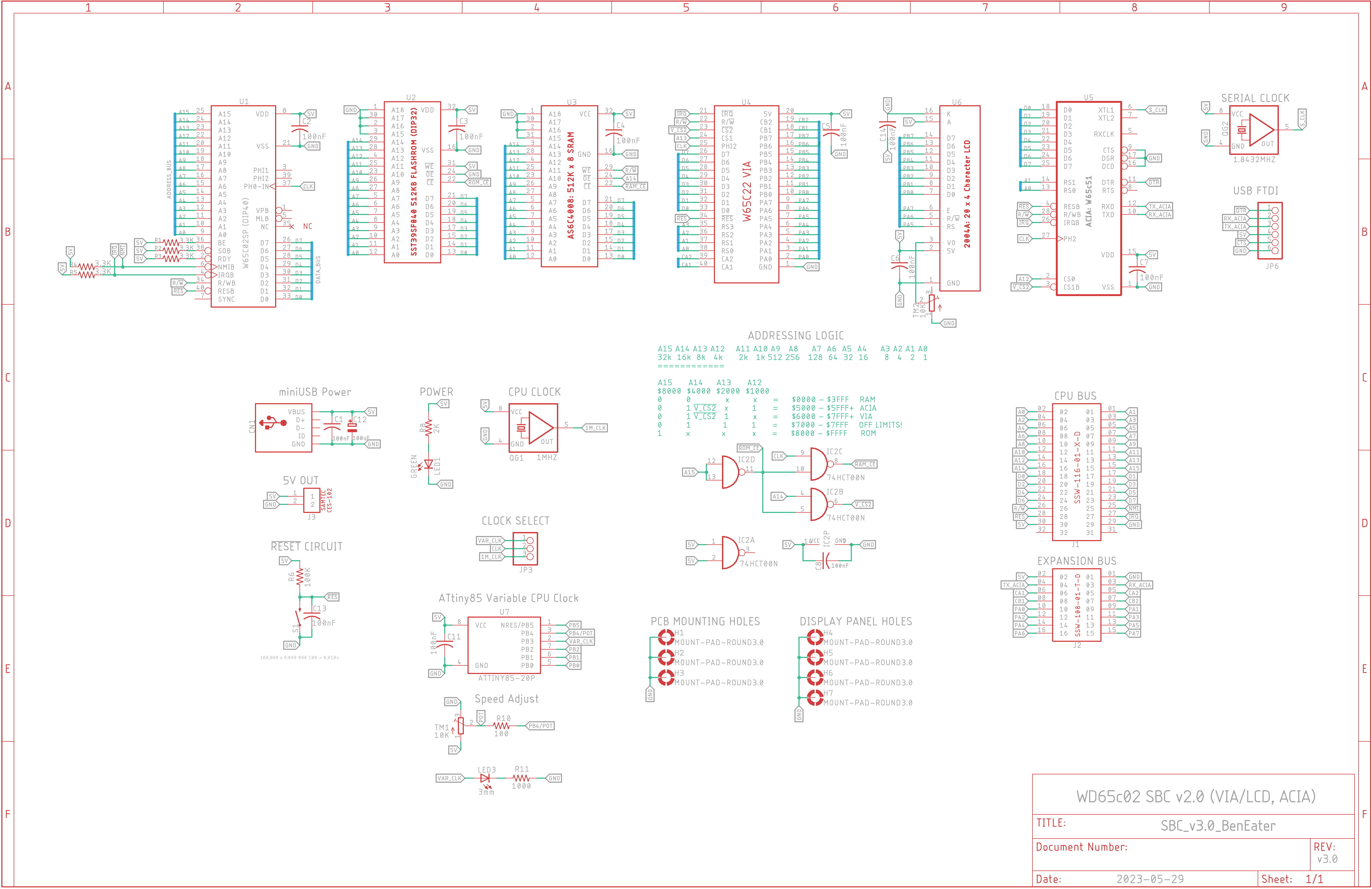
Eagle CAD: v3.0 Schematic
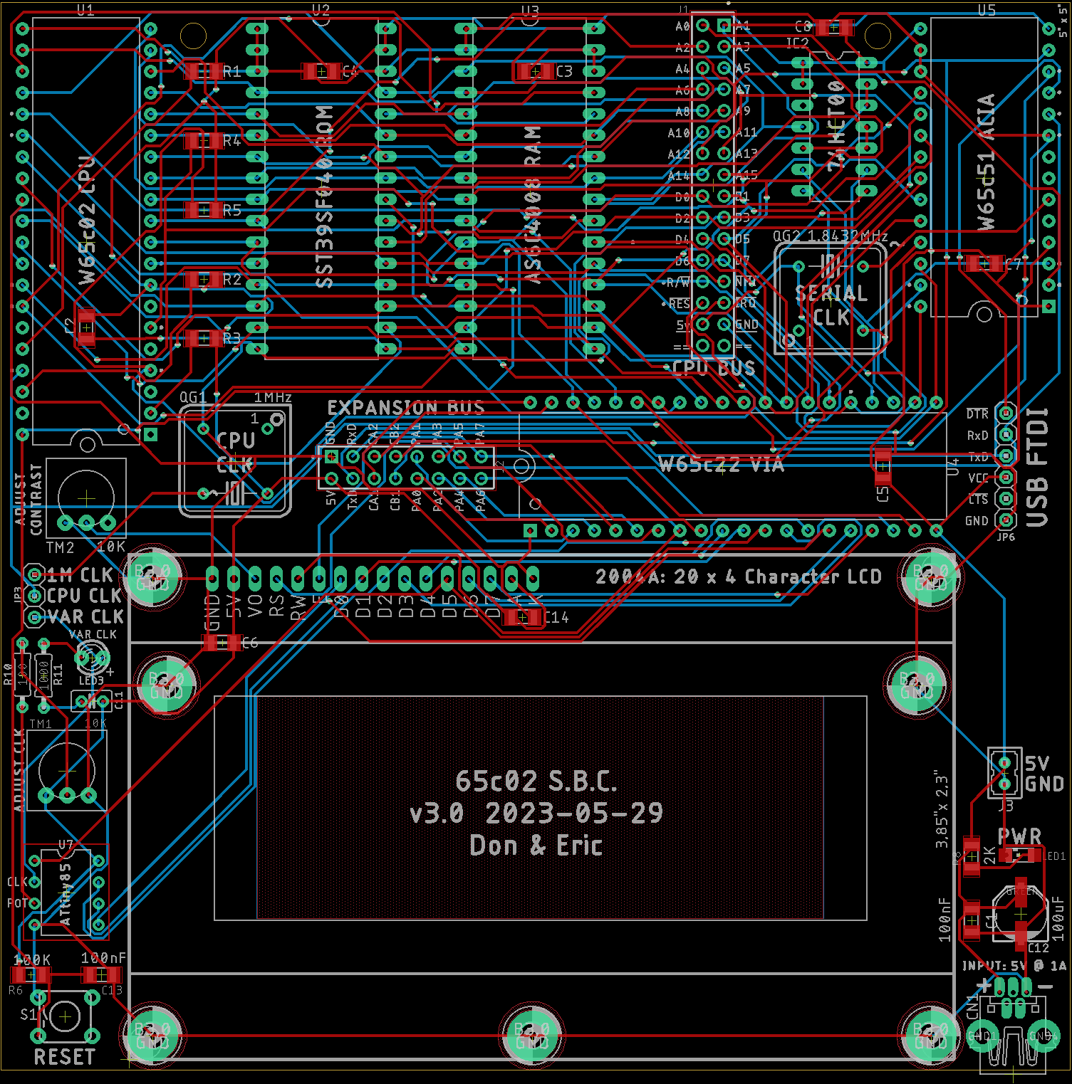
Eagle CAD: v3.0 Board Layout
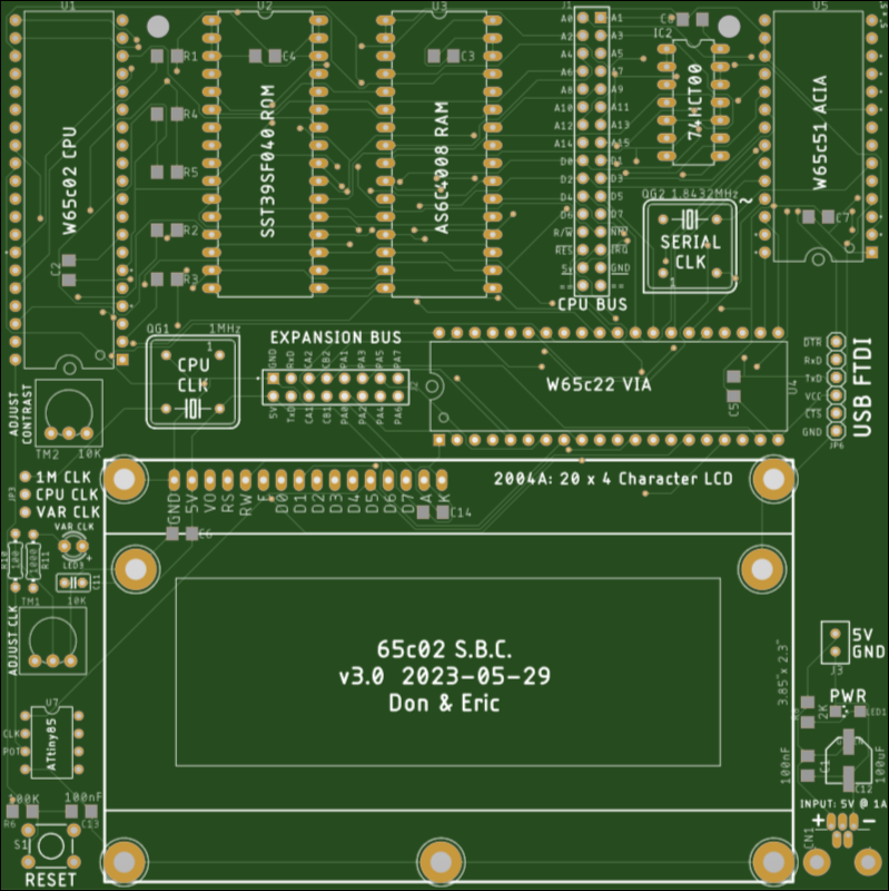
Eagle CAD: v3.0 PCB
Eagle CAD: v3.0 BoM (Digikey.ca)
Short Video: Click to enlarge
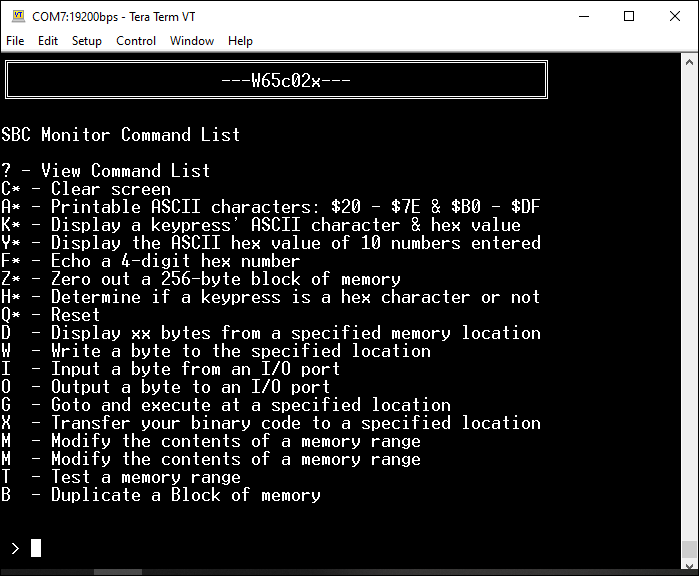
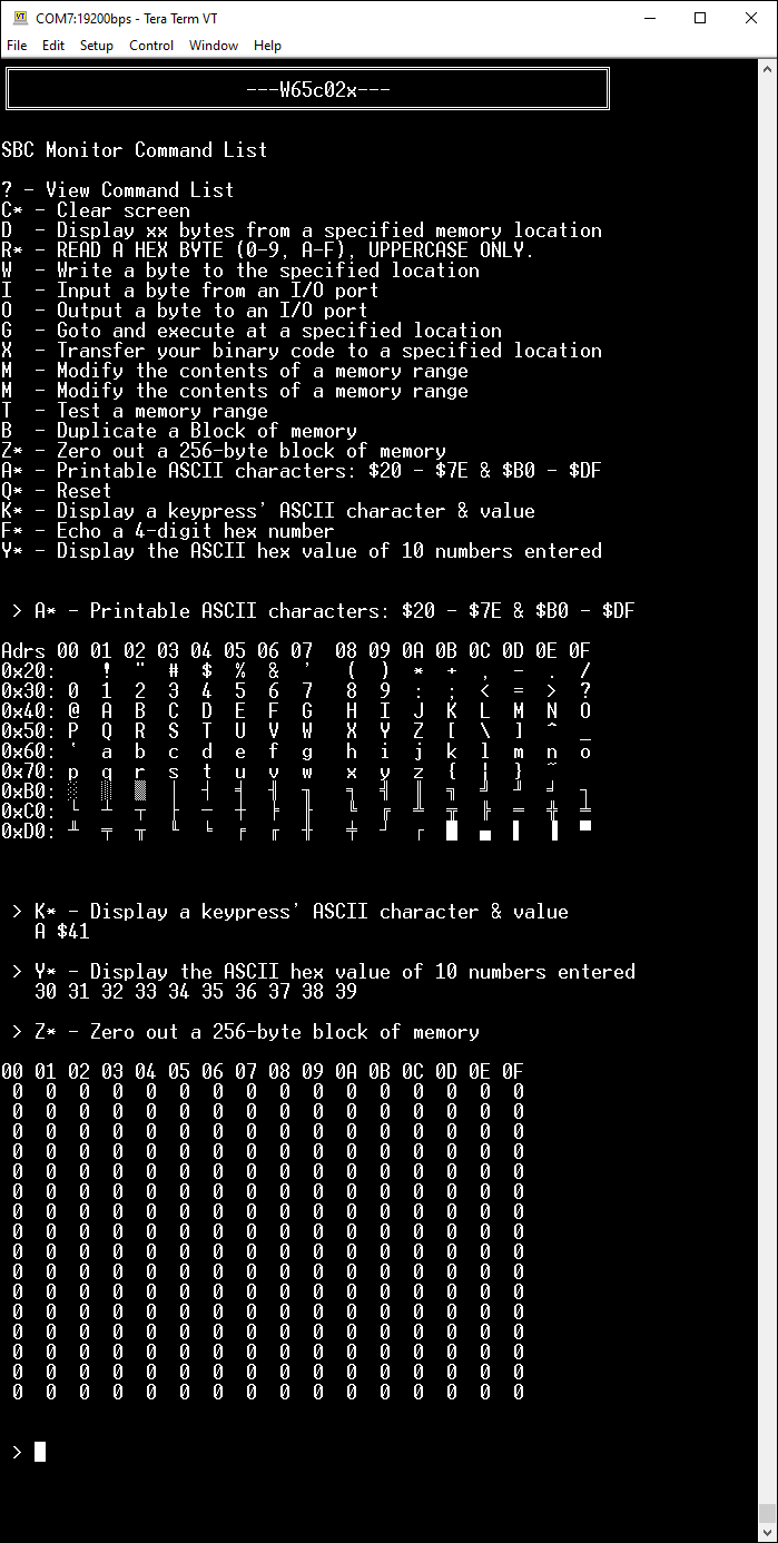
Terminal Screen User Menu
|
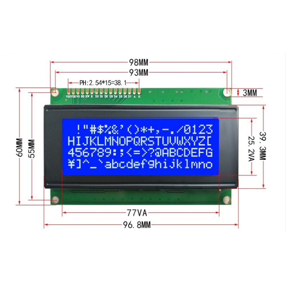
Overview The initial v1.0 design used 32KB for RAM and 32KB for ROM at locations $0000 and $8000, respectively. Power to the SBC is via a 5v miniUSB connector. Typical current draw is under 100mA. The system uses a 1MHz crystal oscillator as well as 0.5Hz to 50Hz variable oscillator, jumper selectable. The 20 x 4 LCD panel (2004A) is driven by a W65c22 VIA (versatile interface adaptor) with data/control starting at address $6000. An ACIA UART was added at address $5000. In the final design (at a much later date), board edge connectors (PC or Eurocard) will be added so that extra boards may be stacked in a backplane with onboard power.
ATtiny85 Variable CPU Clock Full information on programming the ATtiny85 variable CPU clock can be found here.
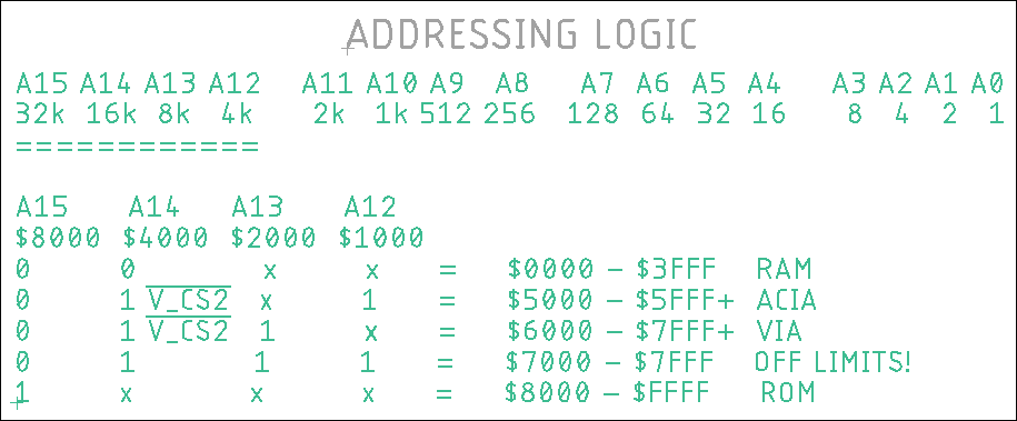
Addressing There were several issues with VIA/ACIA address overlapping which were not resolved until v3.0 of the PCB. The diagram below was taken from the adjacent schematic; this is Ben Eater's addressing scheme and it works. I'm working on another addressing scheme that will double the available RAM.
Serial Communication to the ACIA UART is via TeraTerm v4.1 PC terminal software or PUTTY. The WDC ACIA has a hardware bug that the vendor cannot fix; they insist you add a delay routine between when the TDRE Send Flag asserts (indicating the byte has been converted to bits and has been sent) and when the data is actually sent.
VIA (LCD) & ACIA (UART) Test Code Download SBC3.0_ACIA-VIA.zip that contains the assembly (.asm) code for review and the binary (.bin) code to be burned to a ROM. The assembly code is heavily documented so it shouldn't be too hard to follow along. Startup your terminal emulator and set it for 19200/8/N//1. When the SBC is booted or reset, the banner should be printed on both the LCD panel and in your terminal software. Any key pressed will be echoed only to your terminal screen - not to the LCD panel.
User Menu Code Only 8 of the 20 user menu commands have been implemented so far in SBC3.0_ACIA-VIA__8i.zip ? to see the menu Q or q to reset the SBC C or c to clear the screen A or a to see a table of displayable standard and extended ASCII characters (0x20 - 0x7E, 0xB0 - 0xDF) K or k to see a single key press display as well as its hex value Y or y to see the ASCII hex values of 10 characters you type F or F to echo a 4-digit number (needs work) H or h parses a key press to see if it is hex character: 0 to 9 or A to F Z or z to see a table of zeros when locations $100 to $1FF are "zeroed out". Actually, you would see nothing I swapped $00 for $30, the number 0 ASCII character |
Modern CMOS Parts Used: - CPU: W65C02S - VIA: W65C22 - ACIA: W65C51N - ROM: SST39SF040 - RAM: AS6C4008 - LCD: 2004A - MONITOR: Keye Studio ATMega2560
Here is a great cheat sheet on RS232, ASCII, etc.
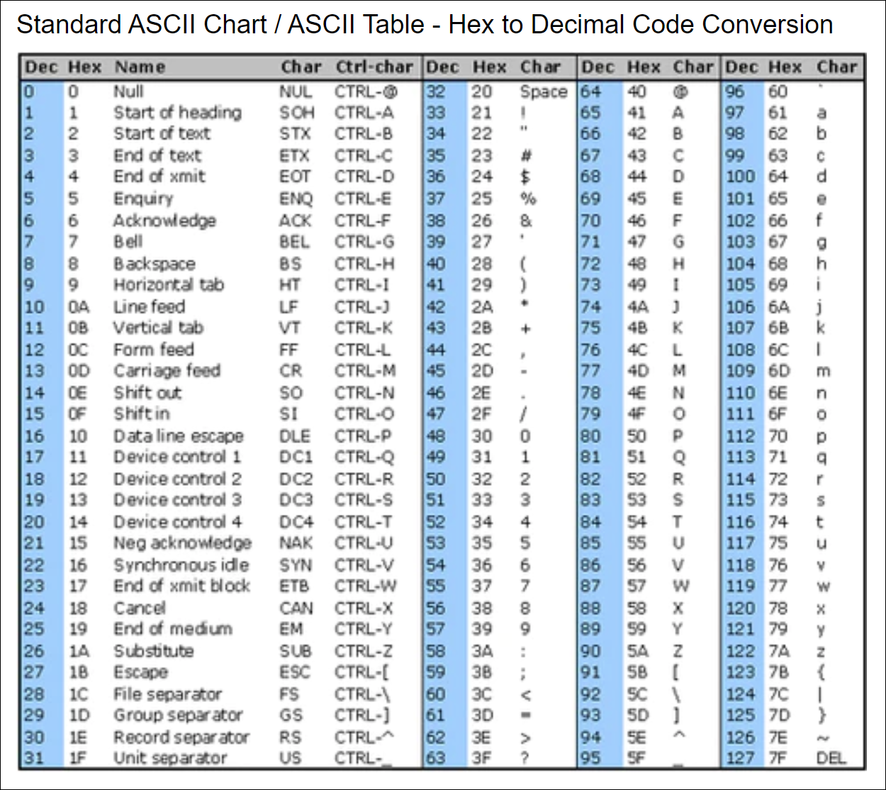
ASCII Chart: Standard
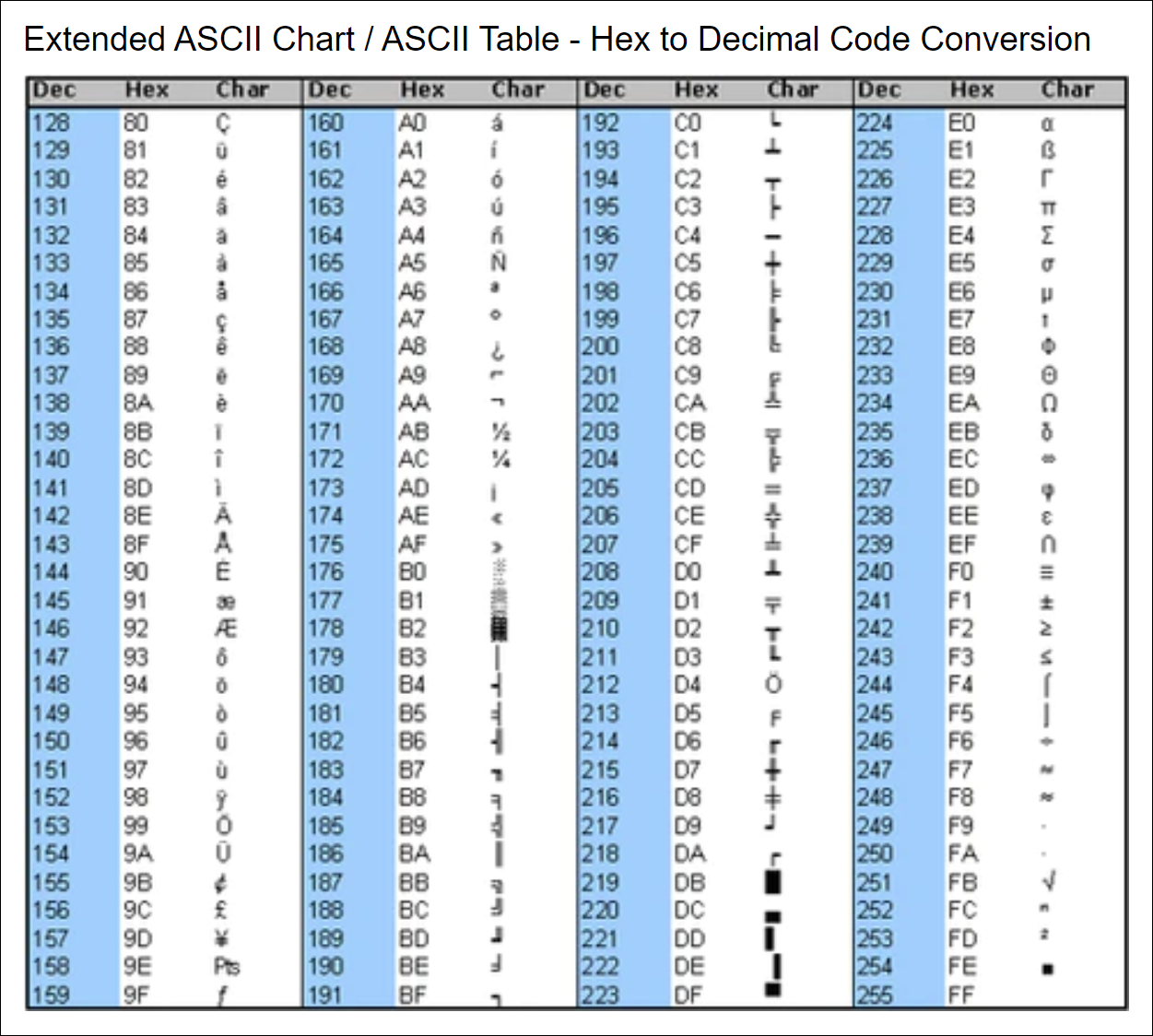
ASCII Chart: Extended
This is what happens when you press "A" or "K", "Y", "Z"
|