![]()
|
Stackable uC: Base Board |
| PCB Circuits (click to enlarge) | Circuits and Info |
|
ATmega328P Microcontroller Breadboard
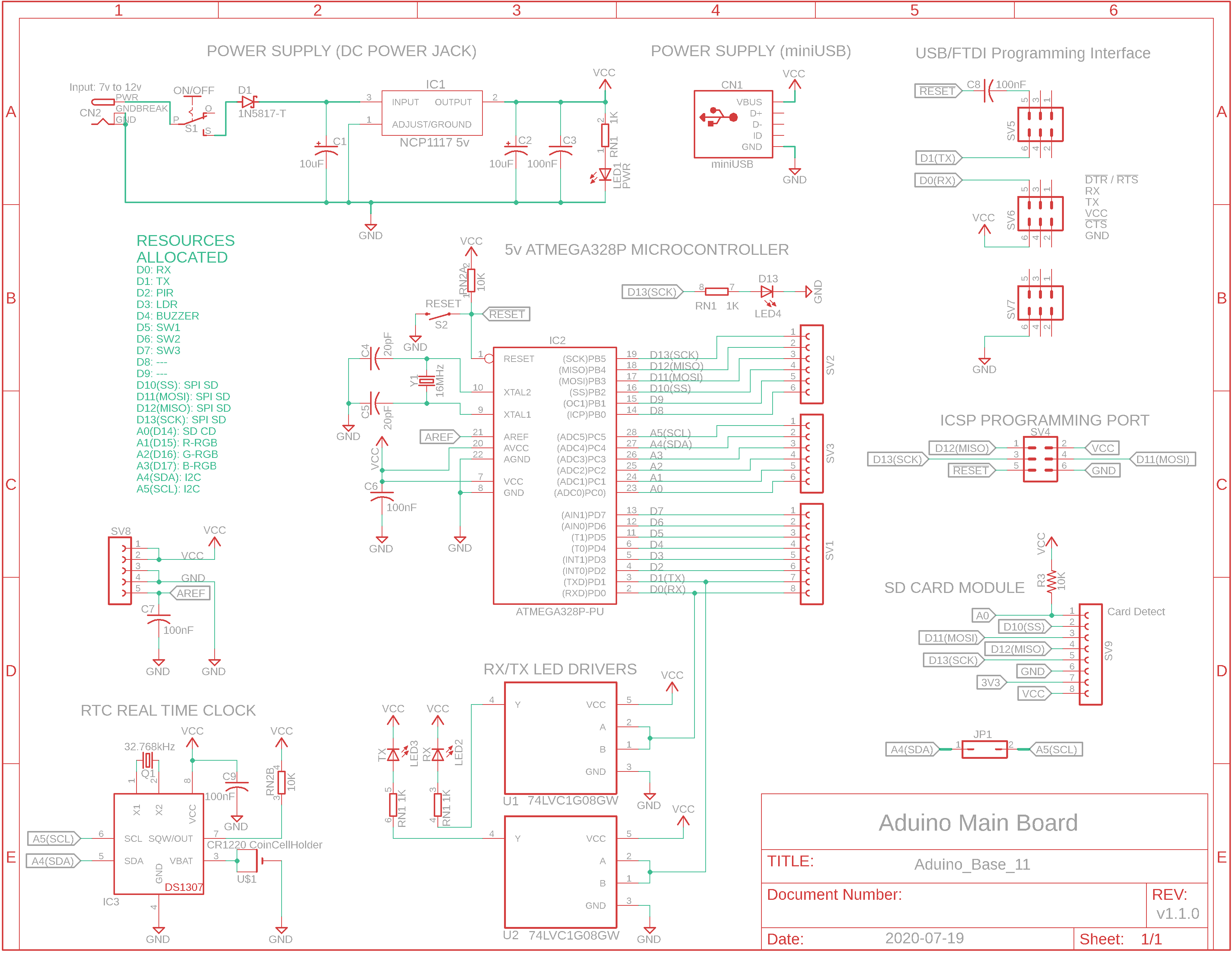
Eagle CAD: 1. Microcontroller Schematic
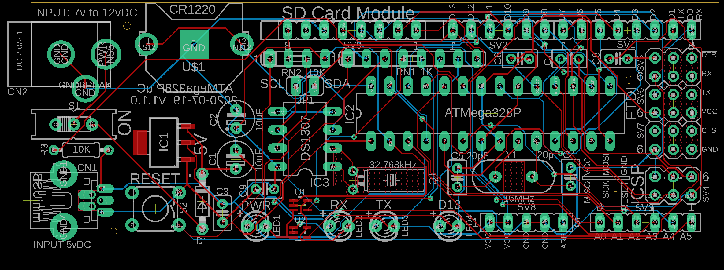
Eagle CAD: 2. Microcontroller Bd. PCB
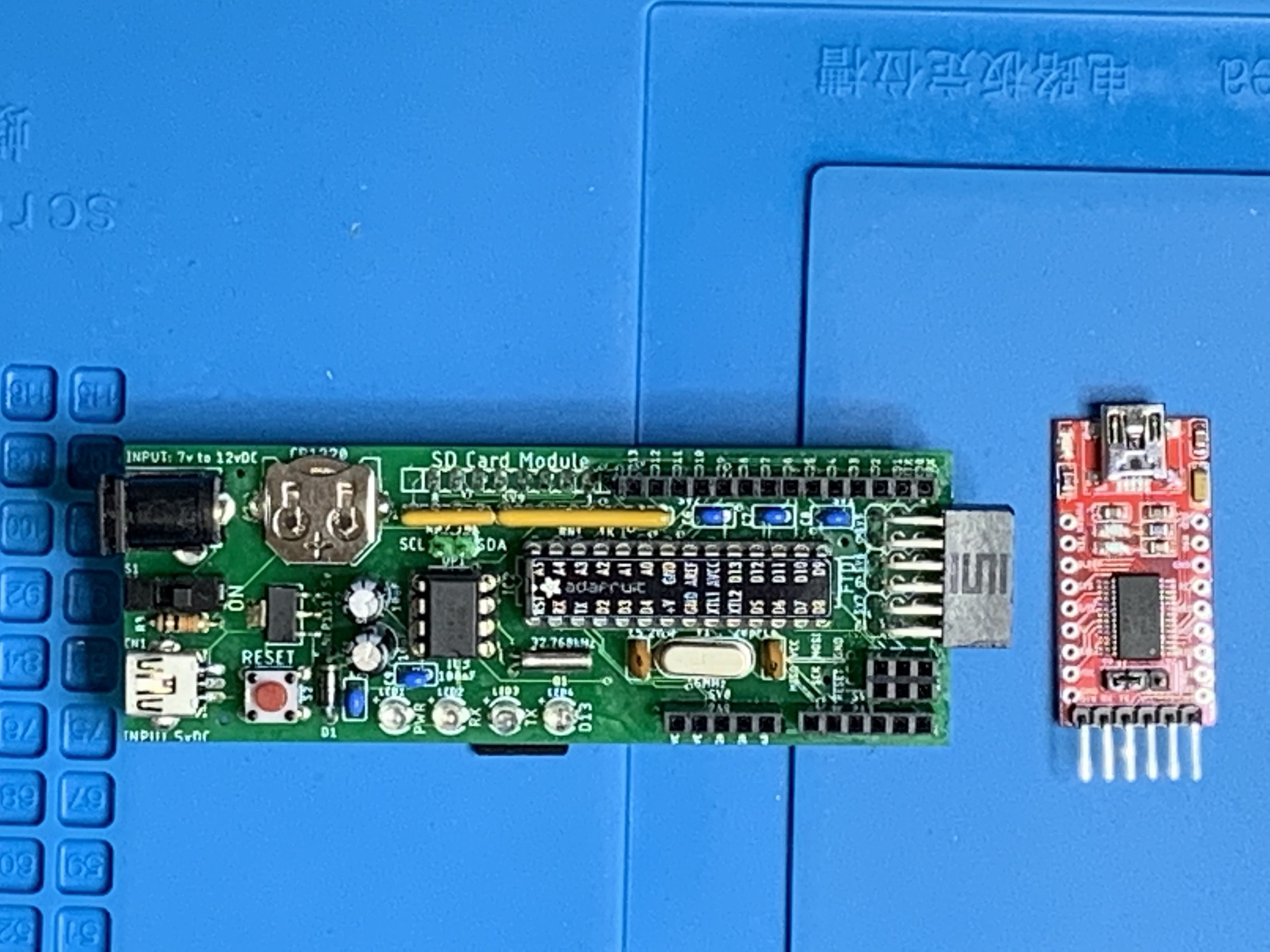
Production: Microcontroller Bd.
Click .gif below for short video
ATMega328P Pinout
(Bill of Materials)
|
Overview There are many Arduino Uno R3-like microcontroller boards on the market. If you try to build your own Uno you've probably been intimidated by the precise soldering required with surface mount devices (SMDs). The alternative is to build a breadboard microcontroller and probably stop there.
In this segment I'm going to build an Uno-like microcontroller board (that uses through-hole electronic components). I'll send the design to my fave PCB production house to have the boards etched. The "fun" will be in populating it with through-hole components when the boards return.
In the top picture in the left panel is a breadboarded Arduino Uno-like microcontroller. Let's keep things simple and just call it a uC which is short for microcontroller. ( μ or Mu is the 12th letter of the Greek alphabet and is commonly used to replace "micro". It is shaped like the letter "u" hence the reason you see uC.) Above and to the right of the ATmega328P uC is a red, inexpensive USB-to-FTDI serial module that plugs into your breadboard or the uC you'll build. We'll use it to upload our code using the Arduino IDE (integrated development environment).
The nice thing about using this configuration is that within the Arduino IDE you don't have to add any additional boards like you would if you wanted to upload code to an ATtiny85 or whatever. You simply select "Arduino/Genuino Uno" and the USB port your Windows 10 PC found when you plugged your USB cable into the USB-FTDI module, then click the "Upload" button. The Rx and Tx LEDs on ports D0(RX) and D1(TX) will flash and a moment later your program will begin to run.
This can be seen in the .gif file near the bottom of the adjacent panel; click it to load a short .mp4 video file. In this short video, I clicked the Arduino IDE Upload button which reset the uC, started and finished the upload, and executed the program that started the blue LED flashing once per second.
The uploaded and running program is nothing more than the Blink.ino sketch found in your Arduino IDE under "File|Examples|01.Basics:Blink".
The schematic and printed circuit board (PCB) layout are also shown adjacent left. Later, I'll be adding an expansion board to the base uC board.
The uC we'll use is the ubiquitous ATmega328P in a DIP20 configuration. In the adjacent images, I added an Adafruit sticker to the top of the IC that shows each pin's name when used in the Arduino environment. Here is the official pinout diagram used for this chip on the Arduino Uno R3 board.
Let's talk about the uC board design: - 2 power sources: --- a barrel connector for "wall wort" power: 7v to 12v DC, max 1A --- a female miniUSB connector for 5v DC power only (no data). Actual current draw with display enabled is 80mA max. --- a 2-connector screw terminal block for 5v DC was removed to make room for the RTC - reverse power protection via low-drop diode D1 - 4 LEDs: power, D13, RX and TX LEDs from D0 and D1 ATmega328P pins - similar design to the Arduino.cc Uno R3 board - labeled ISCP port that can be used for programming or SPI comm. - no built-in USB serial port. You will need to attach a USB-to-FTDI-Serial module that matches the board-labelled pinout - both power sources and the ON/OFF switch are together on the left side of the board - the Reset switch should still be accessible even with a second storey board installed
Micro SD Card Module If we were to keep the ATmega328P uC design to only use through-hole components, there was no room left on the Expansion Board I was also building to house an SD card module, so it was moved to the bottom of the uC base board. Ensure you're using decent SD cards. FAT32 can handle file sizes to a max of 4GB even though the card can be up to 32GB (Microsoft's imposed limit) in storage size so you will need to keep that in mind if datalogging. Please format your SD cards with the original SD Association's formatter utility which can be found here, otherwise they may not report the correct available storage size, etc.
The Arduino Bootloader To write and upload code to the ATmega328P using the Arduino integrated development environment (IDE) currently at version 1.18.xx, you will need to install a bootloader on the ATmega chip. Once done, you can use the USB-FTDI serial module to upload your programs to your new uC anytime. Here's a link that shows how to write the bootloader to the ATmega328P chip using an Arduino board: https://www.arduino.cc/en/Tutorial/ArduinoToBreadboard
Here's a link on how to configure an Uno to program an ATtiny85, in case you need it; you prob'ly won't. |


![]()
Tags: Arduino-type Microcontroller, ATmega328P
![]()