![]()
|
Sketches for Aduino Stackable uC |
Updates
2020-12-19: Different sketches are used with the Aduino M4 Cube due to the enhanced pin assignments used with the Cortex chips.
2020-09-02: The same sketches used with this Aduino (base and expansion boards) can be used with the SBC single board computer, although there are now 5 switches instead of 3.
2020-08-17: Added libraries needed to get some sketches to run. See the highlighted comments near the bottom of this page.
2020-07-19: I've redesigned the base board & expansion board and adjusted the digital and analog pin numbers in the sketches below so that the breadboard and production boards match.
| Click .gif for video | Device & I/O Pins | Sketch | Description/Comments |
|
|
RGB LED - A1, A2, A3 |
|
Red, green, blue LED with common cathode (-) connection.
This program outputs several colours and brightness levels by mixing the input parameters. There are six colour changes. |
|
|
Piezo-Buzzer Speaker - D4, D5, D13 |
Buzzer_01.zip
|
When a switch is pressed, an LED is illuminated and a brief tone/melody is played on the piezo buzzer. The time between the (up to 10) tones can be varied. |
|
|
Switches & LEDs - LEDS: A1, A2, A3 - Switches: D5, D6, D7 |
Switches_LEDs.zip | When a left, center or right switch is pressed, the corresponding red, green or blue LED is illuminated briefly. |
|
|
LDR: Light Dependent Resistor - LDR: D3 - LEDs: A1, A2, A3 |
Three LEDs arranged like a traffic light, illuminate in succession as the light above the LDR is reduced. | |
|
|
PIR Motion Sensor Module - D2 |
PIR_01.zip | The LED connected to D13 will illuminate when the signal from the PIR goes from 0v to 5v after detecting movement. Note how the LED stays lit until the movement ceases. |
|
|
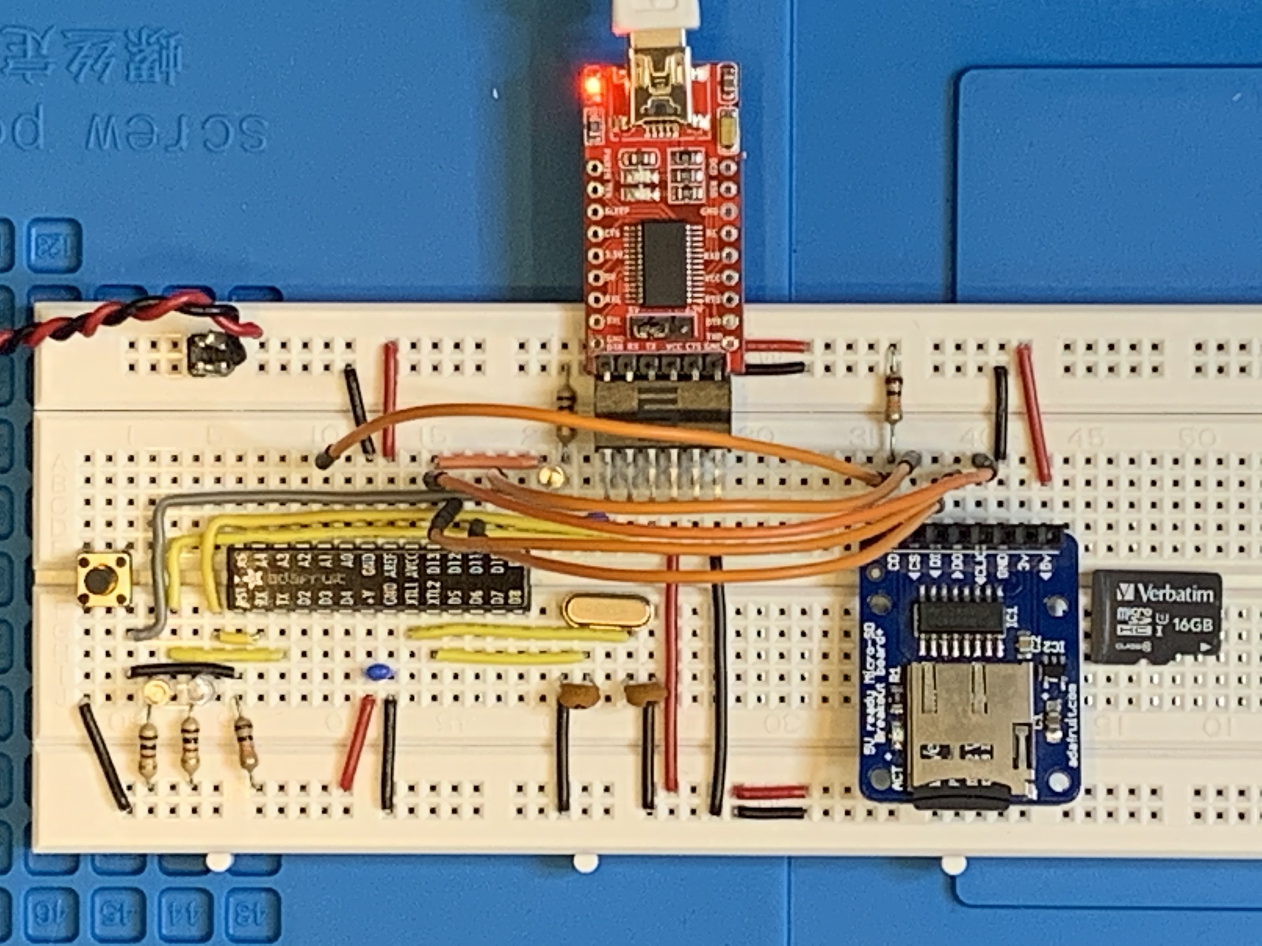
SD Card Module - SPI: D10, D11, D12, D13 - A0 |
Link to more SD functions |
Write a test file to the SD card.
Read the contents of a file previously written to.
List the SD card's files in the root folder.
List the SD card's folders and files. |
|
|
DS1307 RTC Real Time Clock - I2C: A4 (SDA), A5 (SCL) |
DateTime_DS1307.zip
|
Prints the current date, day-of-the-week and
time on the serial monitor. Once initialized by your PC's clock, the
date and time will be backed up by the coin cell battery. This
link will provide info on the RTClib. This program works the same as SdFilesList but now the most recent files are timestamped with the current date & time, thanks to the RTC. |
|
|
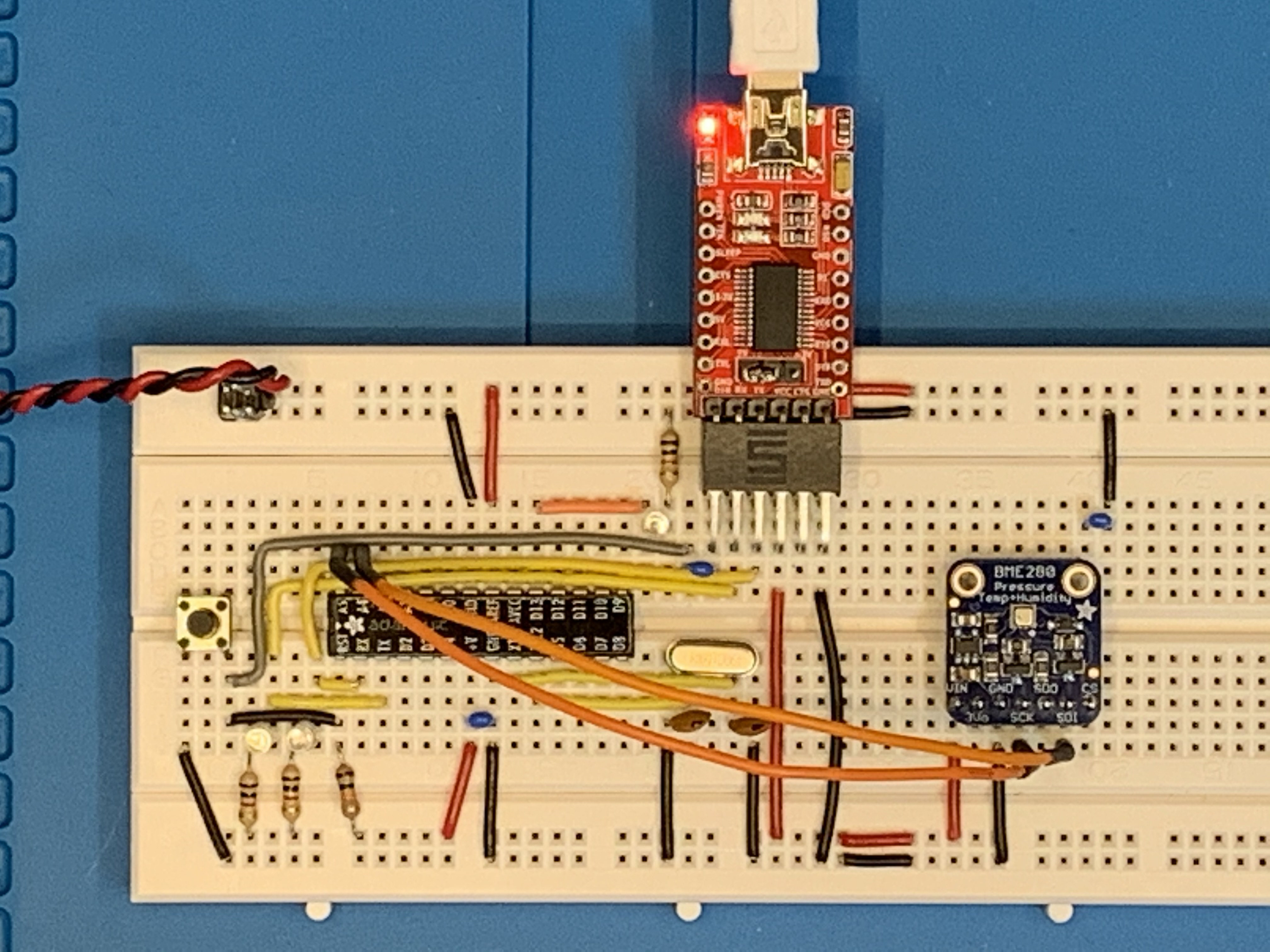
BME280 Sensor Module - I2C: A4 (SDA), A5 (SCL) |
Adafruit sensor provides temperature, humidity and barometric pressure. I included the ability to measure the Humidex temperature (https://en.wikipedia.org/wiki/Humidex#Computation_formula). Altitude can be roughly calculated based on current BP. |
|
|
|
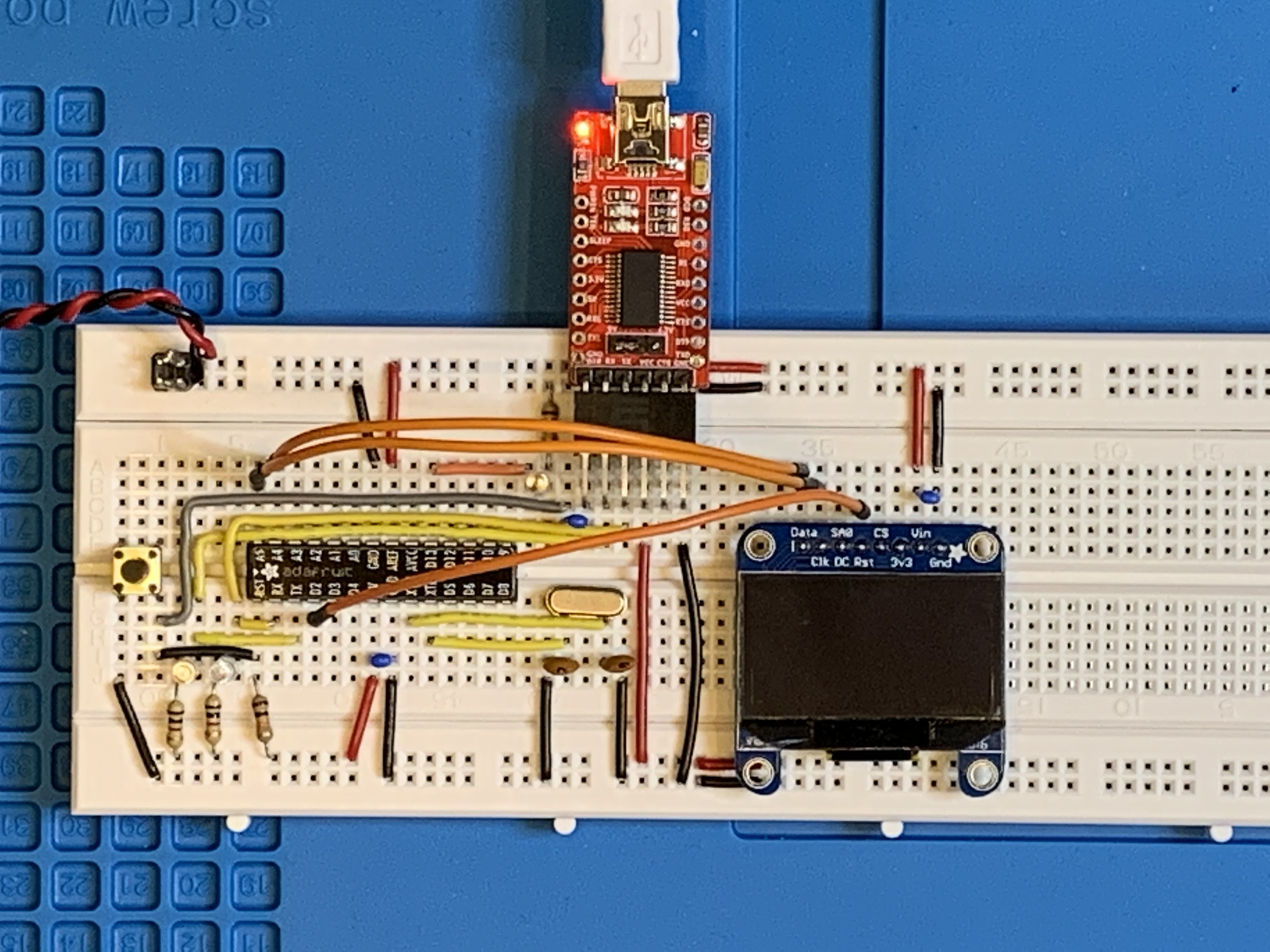
OLED 128x64 Display Module - I2C: A4 (SDA), A5 (SCL)
|
|
Adafruit OLED 1.3" 4-pin 128x64 display test for SSD1306 driver. or Geekcreit OLED 1.3" 4-pin 128x64 display test for SH1106 driver
Note: if the display is missing the left-most column of pixels, switch to the other display driver: SSD1306 versus SH1106.
U8X8 Arduino monochrome text libraries. U8G2 Arduino monochrome graphics and text libraries. |
|
|
OLED, BME and RTC - I2C: A4 (SDA), A5 (SCL) - no Reset |
Weather_Inside.zip
|
Banggood clone of Adafruit OLED 1.3" 4-pin 128x64 but with SH1106 driver, Adafruit BME280 weather sensor, and DS1307 RTC. Using the U8X8 test display library, the sketch used: - 13164 / 32256 program space - 712 / 2048 global variables
You will need these libraries to get the sketch to run: - Adafruit_BME280_Library - Adafruit_BusIO - Adafruit_Sensor - Adafruit_SSD1306 (optional) - Adafruit-GFX-Library (optional) - RTClib - U8g2_Arduino
If your default path is C:\Users\YourName\OneDrive\Documents\Arduino for your sketches, place these libraries (uncompressed) in the "libraries" folder.
|
|
|
OLED, BME, RTC, SD, RGB, and Buzzer - I2C: A4 (SDA), A5 (SCL) - no Reset - SPI (D10 to D13)
|
Weather_Inside_SD_Tone_Flash.zip |
Included weather datalogging every minute to the SD. - 22614 / 32256 program space - 1524 / 2048 global variables |

|
Full system including PIR motion detector - I2C: A4 (SDA), A5 (SCL) - no Reset - SPI (D10 to D13)
|
Weather_Inside_SD_Tone_Flash_2h.zip Example of THBP.txt |
The OLED display is enabled initially to show the stats for 10 seconds and then it's blanked.
The stats are written to the SD card every 60s. (An example can be found in the adjacent column as THBP.txt.)
If the PIR senses movement, the OLED is re-enabled for 10 seconds. The flowchart on the left shows the logical operation. The Arduino code follows this logic.
Below the logic flow diagram is a short video of the working Weather Inside system. You can click on the .gif file for a larger .mp4 video. |
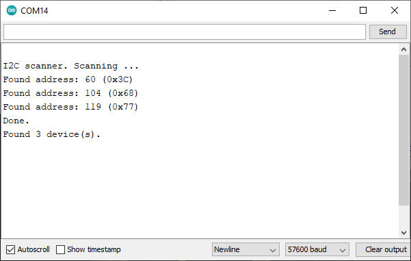 |
I2C Addresses 0x3C: OLED 0x68: SD 0x77: BME280 |
I2C-Scanner.zip |
Q: How do I know which I2C addresses are
in effect? (This becomes important when you cannot get a new device
to work with your current system configuration.)
A: Run I2C-Scanner.zip. It will give you a list of all I2C addresses currently in use. If you don't know which address is which, remove all of the I2C SCL/SDA connections, then add them one by one as you run the program. Use it to document your code for the addresses in use. |

![]()
Tags: Arduino-type Microcontroller, ATMega328P
![]()