![]()
|
Sketches for Aduino M4 Cube |
Updates
2020-12-19: "New" sketches are used with the Aduino M4 Cube due to the increased pin counts and features used with the Cortex M4 chips. Sketch names have "x_" prefix.
|
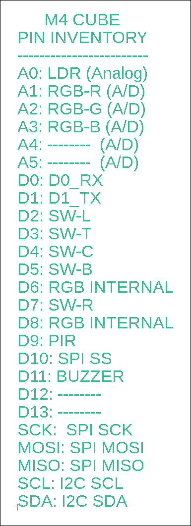
Adafruit Itsy Bitsy M4 Express pin inventory assigned to the M4 Cube development system.
|
|||
|
Cube Board |
Device & I/O Pins |
Sketch Name |
Description/Comments |
|
2 |
RGB LED Circuit Pins A1, A2, A3 |
Red, green, blue LED with common cathode (-) connection. There are six colour changes. This program outputs several colours and brightness levels by mixing the input parameters. |
|
|
1 |
RTC Circuit I2C: SDA, SCL Address: 0x68 |
The default Adafruit DS1307 RTC sketch has not been modified. The library is attached as RTClib-master.zip |
|
|
1,2,3,4 |
I2C I2C: SDA, SCL Address: all |
Enumerate all I2C ports in your system. If you don't know which address is which, remove all of the I2C SCL/SDA connections, then add them one by one as you run the program. Use it to document your code for the addresses in use. |
|
|
2 |
OLED Display Module I2C: SDA, SCL Address: 0x3c |
1.3" 128x64 OLED display with SSD1306 driver chip. Default Adafruit sketch has been modified for 4-wire operation on an address alternate from 0x3D. U8X8 Arduino monochrome text libraries. U8G2 Arduino monochrome graphics and text libraries. |
|
|
2 |
5 Button Switches D2, D3, D4, D5, D7 |
Pressing each switch lights up an LED colour combination. L,T,C,B,R (Left, Top, Center, Bottom, Right) |
|
|
2 |
Piezo-Buzzer Circuit D11 D2, D3, D4, D5, D7 A1, A2, A3 |
Sketch to test buzzer circuit using left switch and red LED of RGB LED. Another test sketch: when a switch is pressed, an LED is illuminated and a brief tone/melody is played on the piezo buzzer. The time between the (up to 10) tones can be varied. |
|
| 2 |
PIR Motion Sensor Module D9 |
x_PIR_02.ino | Red LED on pin A2 illuminates when motion is sensed by the PIR. |
|
3 |
BME280 T/H/BP Sensor I2C: SDA, SCL Address: 0x3c |
x_BME280_OLED_Test.ino |
I included the ability to measure the Humidex temperature (https://en.wikipedia.org/wiki/Humidex#Computation_formula). Altitude can be roughly calculated based on current BP. Test just the BME280 sensor output on the OLED and Serial Monitor. |
| 3 |
Micro-SD Board SPI: D10 (SS), SCK, MOSI, MISO |
x_BME280_OLED_RTC_SD_Test.ino
Link to more SD functions |
A continuation of the test above but with RTC and SD. Write a test file to the SD card. Read the contents of a file previously written to. List the SD card's files in the root folder. List the SD card's folders and files. |
|
3 |
LDR: Light Dependent Resistor LDR: D3 LEDs: A1, A2, A3 |
LEDs will light up in succession from red to green to blue as the light level being read by the light dependent resistor is reduced |
|
| 3 |
Quad 7-Segment LED Module I2C |
HT16K33.ino |
You will need the Adafruit library for this I2C device. For the final test of all systems, upload Weather_Inside_M4_g.ino |
![]()
Tags: Arduino-type Microcontroller, ATsamD51 Cortex M4
![]()