![]()
|
Aduino (Large Box) M4 SBC |
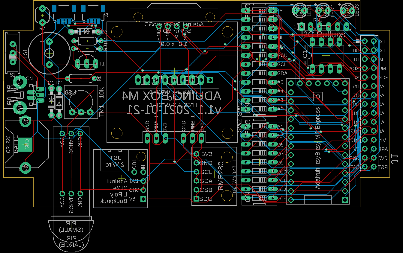
| PCB Circuits (click to enlarge) | Circuits and Info |
|
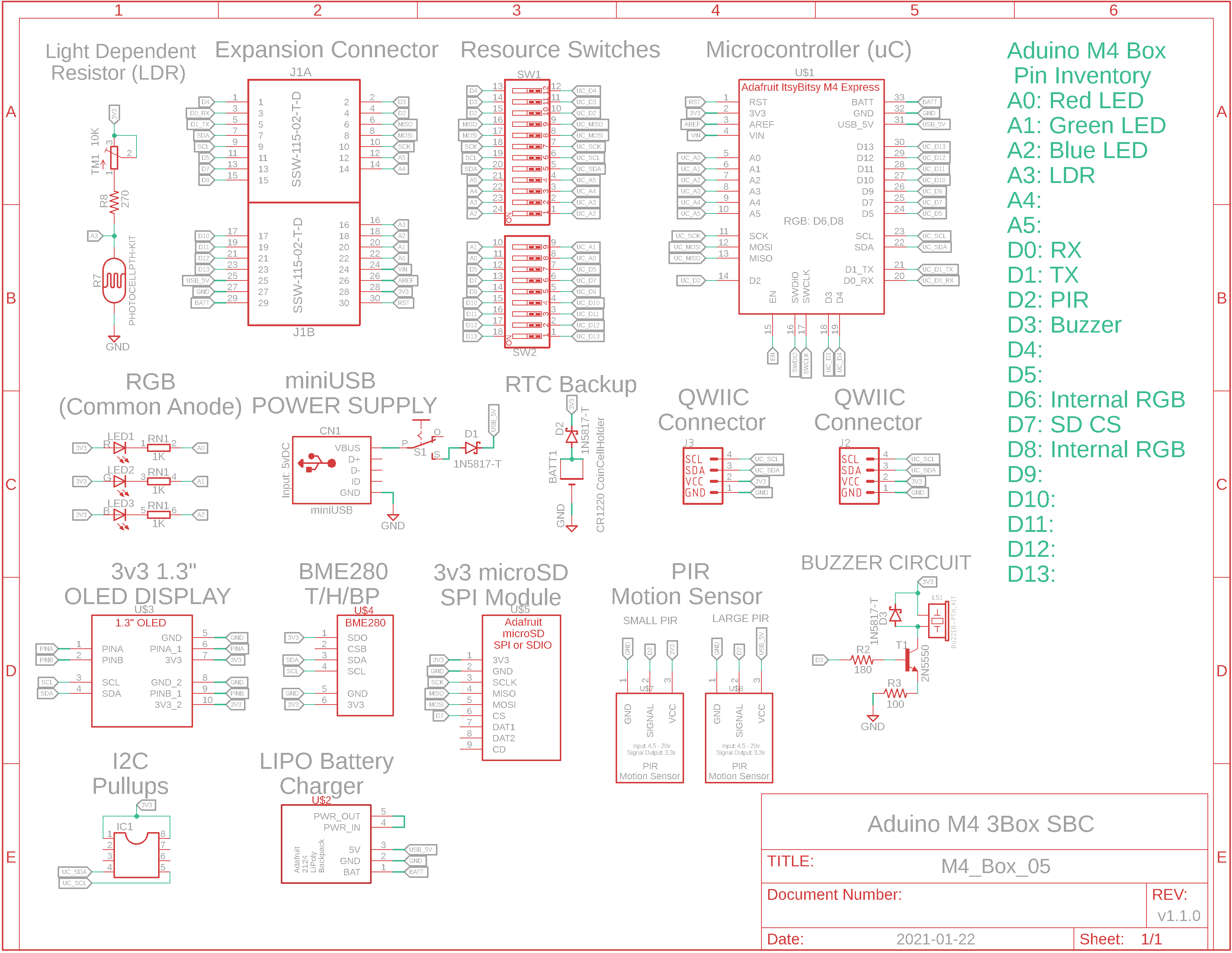
Eagle CAD: v1.1 Schematic 1
Eagle CAD: v1.1 Schematic 2
Cutie M0 Resources Allocated
(Bill of Materials, modules are not included) |
Overview This fourth weather station will be a cross between the multiboard Cube M4 and the SBC Cutie M0. It is designed to fit inside a Hammond 2.45"W x 4.45"L x 1.22"H project box. We'll use the Adafruit Itsy Bitsy M4 Express microcontroller which supports Arduino C/C++ or CircuitPython programming environments (2MB SPI Flash). The expansion connector on the right side connects directly to the M4 microcontroller. With the ability to switch out devices like the RGB LEDs, LDR, PIR, Buzzer and SPI to the microSD, you could make this your development platform to add other devices.
Weather Station There are several resources installed on the SBC to function as a type of weather station that can provide: - display of the current stats: temperature, humidity and barometric pressure values - calculation of Dew Point and Humidex - data logging to a microSD card
Microcontroller Resources The M4 Express uses a Microchip ATSAMD51G 3v3 microcontroller with the following resources: - 120MHz, 512KB Flash for program storage, 192KB dynamic SRAM for global variables, 2MB SPI Flash for CircuitPython code storage if you're not using the Arduino IDE (apparently you can switch back and forth between these two programming languages). This is soooo much more than the original Atmel ATmega328 and it means you can finally run graphics on the OLED without draining all of the SRAM - native USB for programming and serial monitor debugging - I2C and SPI serial ports - 3.3v operation, reset button and pin - many, many more features. Check out the Microchip datasheet or Adafruit's .pdf on the ItsyBitsy M4 Express microcontroller breakout board
I2C Devices like the 1.3" OLED and BME280 sensor utilize I2C for communication. Additional I2C devices can be connected via the two 4-pin QWIIC connectors at the left side of the back of the PCB. Here are links for cables and connectors: - QWIIC cable - QWIIC JST SH 4-pin vertical connector -
QWIIC JST SH 4-pin right-angle
connector
SBC Features: Not all of the Cube M4 functions are present on this much smaller SBC. As such there are a lot more GPIO resources left over (9 pins). All of the pins except I2C in use on the uC can be switched out so you can use the pins for other purposes. The expansion connector for all of the uC pins extends out the right side of the Hammond box. The "millis_RTC" library is used instead of an onboard real time clock. The uC time is backed up with a CR1220 coin cell battery. There are two QWIIC connectors on the back of the box for I2C expansion. You can change the I2C pull up resistors at socket IC1 (Adafruit intentionally does not provide any) to accommodate an increase in bus load due to an increase of I2C devices. Power to the board is via the miniUSB connector (power only, no data) on the left side of the box or via the uC USB-C connector on the front of the box. Due to the poor availability of RGB LEDs, three separate LEDs are used in the top right corner of the PCB. Due to the odd availability of PIRs, the board is wired for both full length and short PIRs on the bottom of the board. One PIR uses 5v for power whereas the smaller one uses 3v3; both output a 3v3 signal to pin D2.
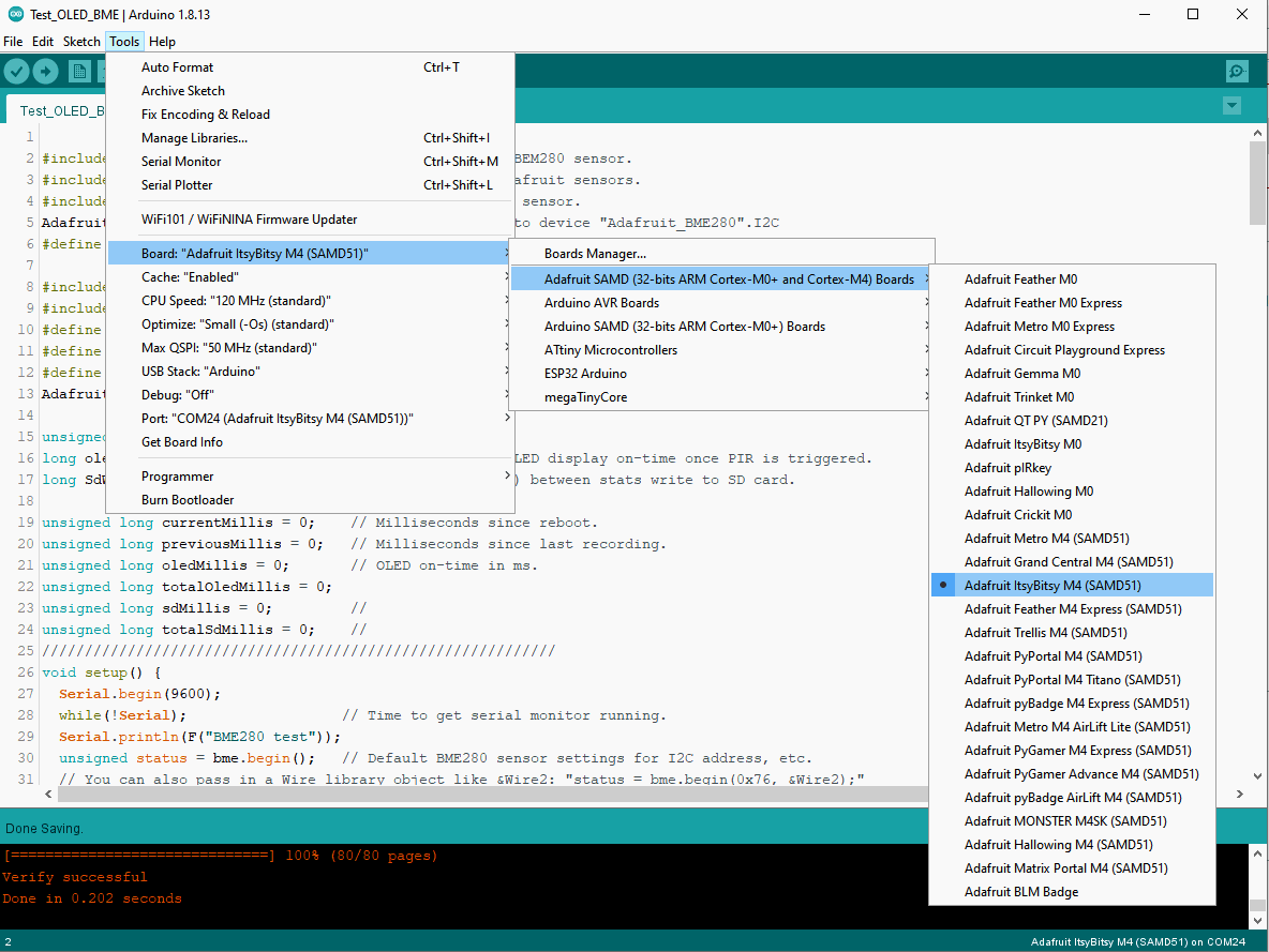
USB programming and power Arduino IDE should be configured for "Adafruit ItsyBitsy M4 (SAMD51)". Here is a link to installing and configuring the device The Aduino Box M4 SBC can be powered via 5v miniUSB (the M4 converts it to 3.3v) or via the M4's microUSB connector.
Devices/Modules Included: - Built-in RGB DotStar LED on M4 uC module - Available LiPoly backpack to attach a rechargeable battery to the M4 Express uC module - 128 x 64 OLED monochrome display - microSD card module for data logging - BME280 Temperature/Humidity/Barometric Pressure module - LDR light detecting resistor - Motion sensing Passive Infrared (PIR) sensor, could be used to sense movement to enable the OLED display, etc. - Buzzer for alerting, playing tones, etc.
Sketches Each major change to the PCBs used in the Weather Inside project requires a change to the final test program. You should consider using the following sketch to test your PCB as you solder in each function's components: x_WI_Box_M4_j.ino
PCBs have been sent to China for fab. I will post a short video demonstrating operation when the boards return. |
|
|
|
![]()
Tags: Arduino-type Microcontroller, ATMega328P
![]()