![]()
|
Aduino (Small Box) M0 SBC |
| PCB Circuits (click to enlarge) | Circuits and Info |
|
Video of breadboard Aduino M0 1Box v1.0
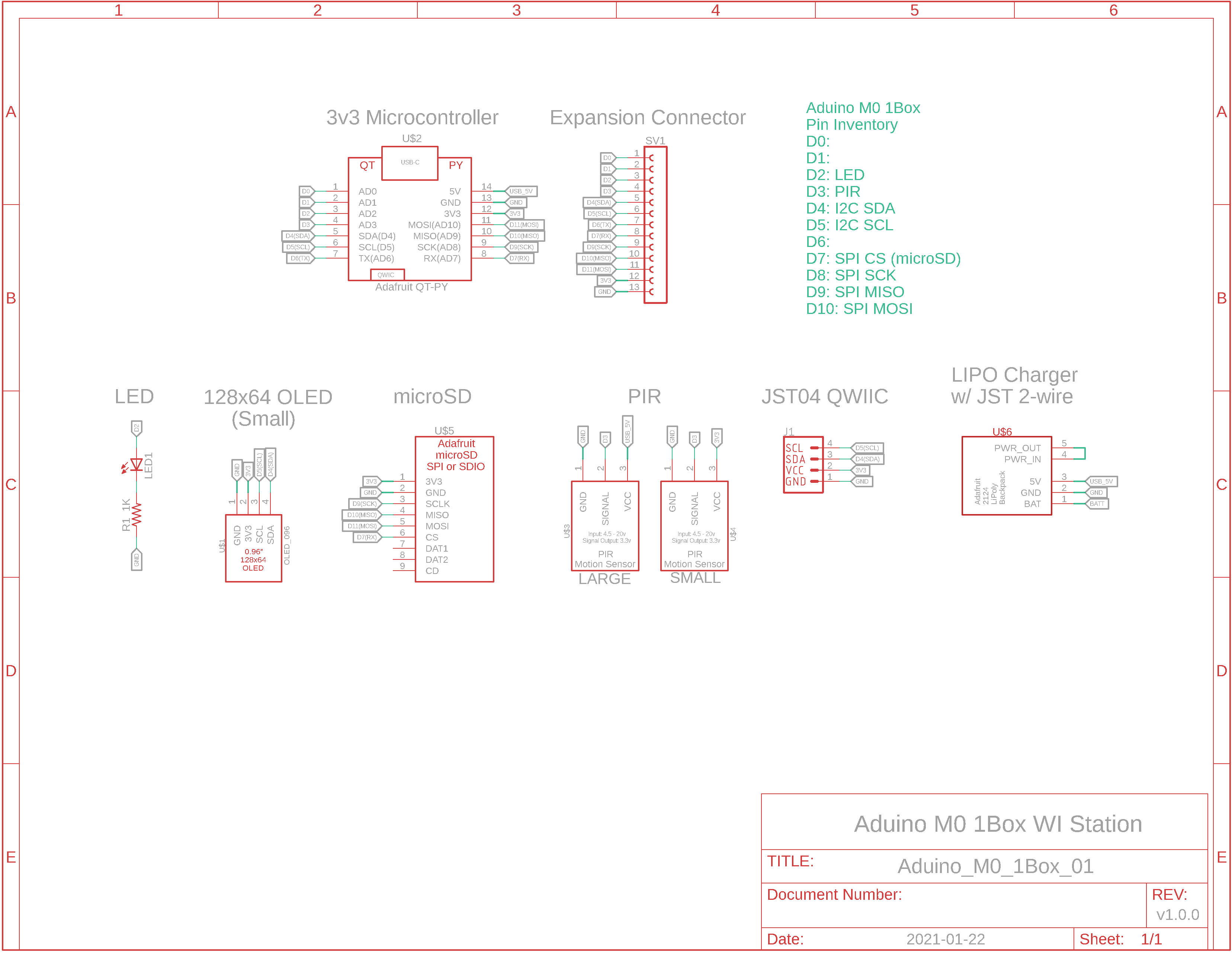
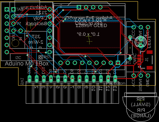
Eagle CAD: v1.0 Schematic 1
Eagle CAD: v1.0 Schematic 2
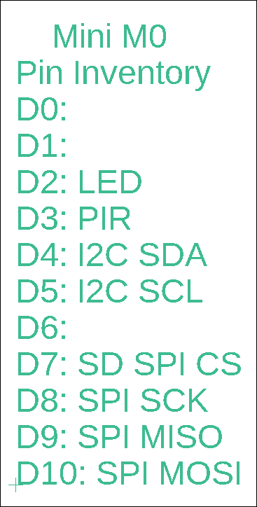
Mini M0 Resources Allocated
(Bill of Materials, modules are not included) |
Overview This is the smallest (of the 6) weather stations and is designed to fit within a 1.36"W x 2.35"L x 0.79"H plastic box (Hammond 1551H). It has been designed as a dev system thanks to all of the pins ported out to a female connector at the back of the tiny box.
Features: - 2-wire JST connector for LIPO charger, both of which are on the bottom of the board - both mini PIR and regular PIR are supported, and should be mounted on the bottom of the board - 12-pin right-angle female header on the rearside of the SBC includes 3v3 power to other devices you may wish to attach to this dev board - 4-wire Qwiic JST connector moved to the bottom of the back of the board for connection to your I2C devices - 0.96" 128x64 white OLED
Weather Station There are several resources installed on the Cutie M0 to function as a type of weather station that can provide: - temperature, humidity, barometric pressure, dewpoint and humidex values - display of the current stats - data logging of the stats
SBC Flexibility This SBC can be expanded as a development system thanks to female header SV1 on the rear side which makes available all of the 11 GPIO pins (D0 to D10) from the Cortex M0 microcontroller.
Sleepy? You can replace the "delay(milliseconds)" statements with "LowPower.deepSleep(milliseconds)" statements - there's 3 of them - which will reduce current consumption from about 50mA to under 20mA using the "ArduinoLowPower.h" library, but you may get weird behaviour. For instance, Windows 10 produces a "positive" chime when it finds the USB-C port on your mini board and a "negative" chime when it loses the port. Expect to hear the port chime negatively when the port is lost until movement is detected by the PIR and Win10 finds your port again. Also, you may not be able to reprogram the board unless you hit its Reset button twice. That is why the "delay()" statements are used in the sketch and the "LowPower.deepSleep" ones (and the library) are commented out.
Microcontroller Resources Microchip ATSAMD21E18 Cortex M0 3v3 microcontroller: - 48MHz, 256KB Flash for program storage, 32KB dynamic SRAM for global variables. This is soooo much more than the original Atmel ATmega328 and it means you can finally run graphics on the OLED without draining all of the SRAM - native USB for programming and serial monitor debugging - I2C and SPI serial ports - 1.62v to 3.63v operation - many, many more features. Check out the Microchip datasheet or Adafruit's .pdf file on the QT PY
Adafruit Drivers & Libraries Make sure you follow the directions found at https://learn.adafruit.com/adafruit-qt-py/using-with-arduino-ide to install the drivers and libraries for their QT PY microcontroller.
I2C Devices like the 1.3" OLED and BME280 sensor utilize I2C for communication. Additional I2C devices can be connected via the tiny STEMMA QT / Qwiic JST SH 4-pin connector on the Adafruit QT PY board. You can see the cable plugged into the top left corner of the video in the adjacent column. Here are links for cables: - https://www.adafruit.com/product/4209 - https://www.adafruit.com/product/4210 -
https://www.adafruit.com/product/4401
SBC Features: - USB programming and power: Arduino IDE should be configured for "Adafruit QT PY (SAMD21)". Here is a link to installing and configuring the device - The SBC can be powered via 5v miniUSB (the QT PY converts it to 3.3v) connector or via the USB type C connector on the QT PY board - 11-pin expansion connector (D0 to D10), 5-wire power connector - 2-wire Qwiic connector to attach a LiPoly battery
Devices/Modules Included: - USB programming via USB-C connector on Adafruit QT PY microcontroller USB C connector - 128 x 64 0.96" OLED monochrome display - microSD card module for data logging - Soft RTC. Install the RTClib library for use with the sketch. The current time is backed up with a CR1220 coin cell battery - Adafruit-compatible BME280 Temperature/Humidity/Barometric Pressure module - Motion sensing Passive Infrared (PIR) mini sensor, could be used to sense movement to enable the OLED display, etc. - Expansion via the Qwiic JST SH 4-pin I2C connector, or via the right-side dual right-angle connector
Sketches Use the QT-PY specific sketch, x_WI_General_L.ino, with this Aduino SAMD21 development board. You will need to modify either line 17 or 18: one of them must be commented out with "//", depending on whether your OLED uses the SSD1306 or SH1106 driver. The adjacent video shows the round-hole OLED board using the SSD1306 driver. Commonly, the oval-hole OLED board uses the SH1106 driver. Note that this is a general usage Weather Inside sketch that has been modified for this board. You can modify it easily to suit any of the other microcontroller boards. |
|
|
|
![]()
Tags: Arduino-type Microcontroller, ATMega328P
![]()