| SMT 3v3 / 5v 5-Amp Power Supply Module | ||
|
Pix/Vids/Schematics (click to enlarge) |
Info |
|
|
5A/5V Power Supply (Long) v1.1 Schematic
5A/5V Power Supply (Long) v1.1 Board Layout
Image Showing Operation of v1.0
Eagle CAD: v1.1 BoM
Eagle CAD: Digikey.ca v1.1 BoM
v1.1 PCB is out for fab
|
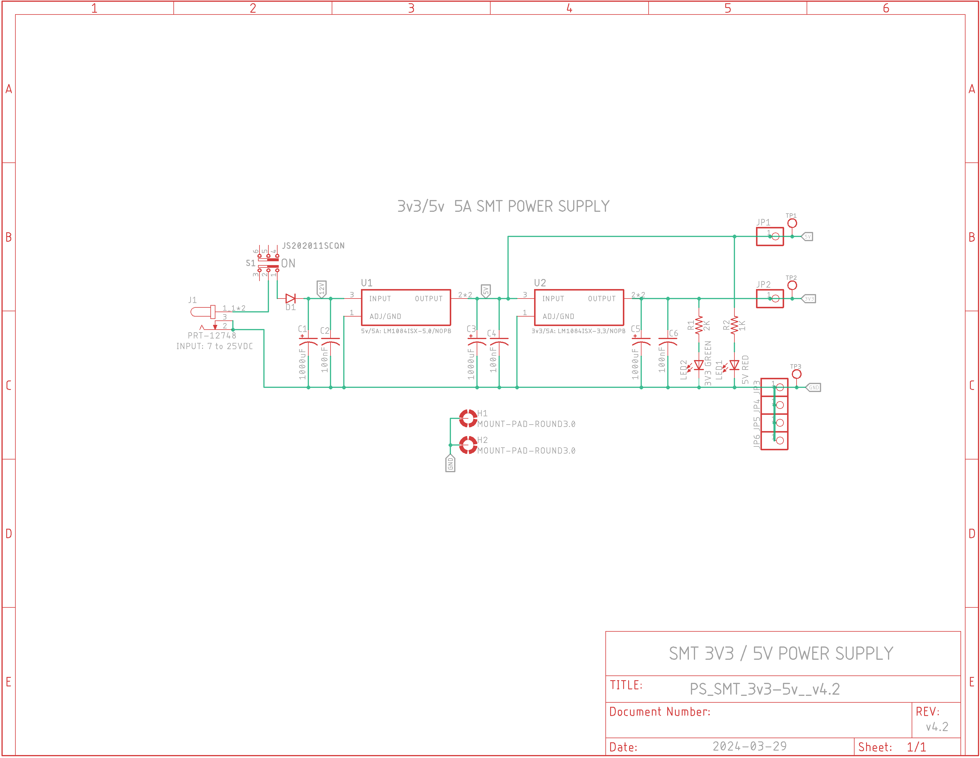
v4.2 Schematic
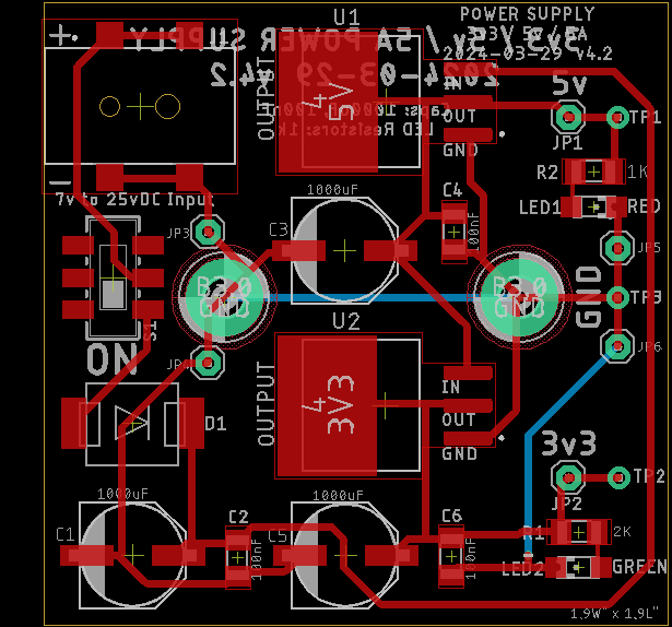
v4.2 Board Layout
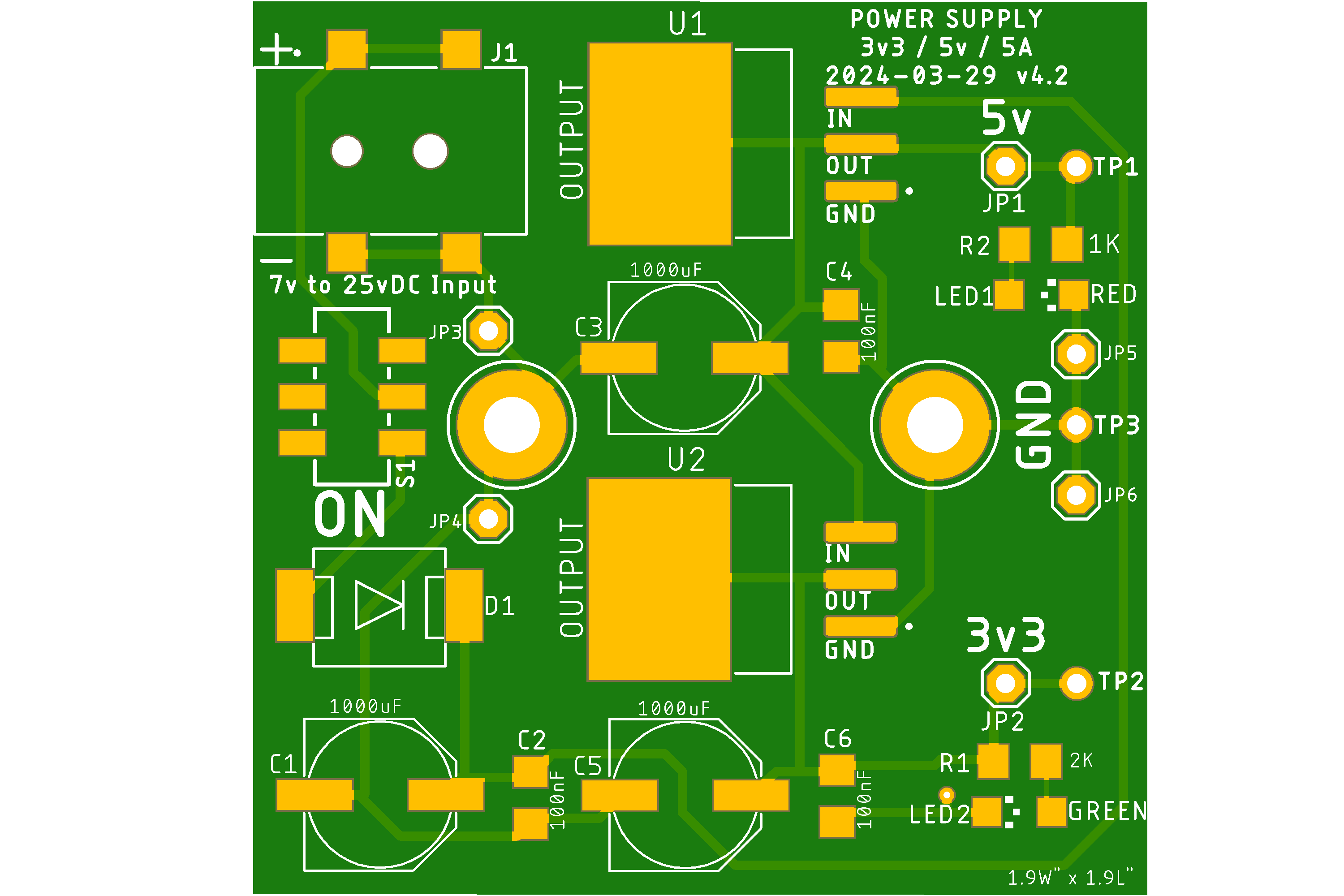
v4.2 PCB Top
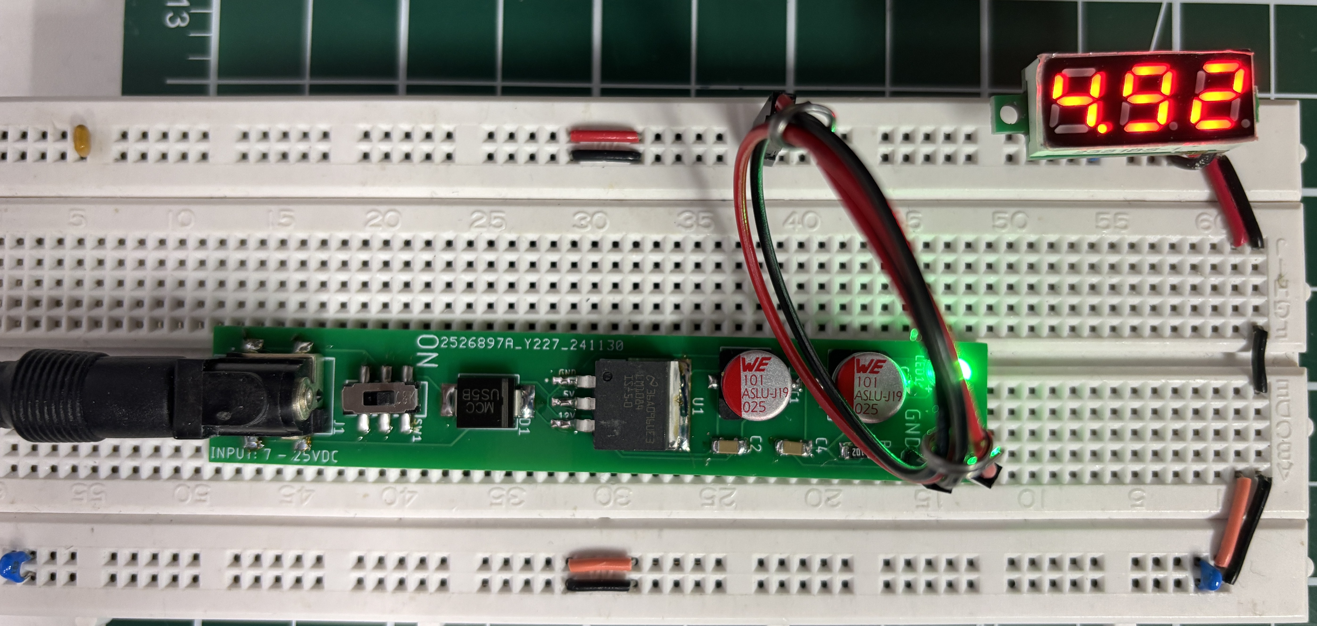
Short .mp4 Video (enlarge)
|
Description: Three power supplies are shown here: two 5V and a 3v3 / 5v version. Dual voltage 3v3/5v power supply is designed to be attached to your breadboard or soldered to your next PCB design (the two left GND jumpers provide physical support).
Features: - 3.3v and 5v DC output with power LEDs for each - Both 5v and 3.3v voltage regulators are 5A rated - With the exception of the male header pins and test points, all discrete components are SMT with a minimum size of 1206 for easier hand soldering
Power Input: - 2.1mm DC barrel jack: input 7v to 25vDC
Power Output: - 3v3 DC and 5v DC to a 'split' breadboard as shown in the v3.0 adjacent video at the bottom - Output current limit is up to 5A regulated by LM1084ISX and LM1585
v4.2 Features: - Separate 5 amp voltage regulators - Larger input polarity protection diode - On/Off switch problem fixed - 3 test points - 2 grounded mounting holes |
|
v1.1 Long 5A/5V Power Supply: - Attach it to your upper 5v rail. There are two contact points for a secure fit. - Can run up to 5A for 5V and can be switched off - This power supply was needed to run dot LED Matrices with ESP32; its cheap 5v current regulator from USB cannot handle anything over 100mA or so
|
||


![]()
Updated 2024-12-24 @ 8am
![]()