![]()
|
Project 27: Atmel ATmega328, ATtiny84 and ATtiny85 |
|||||||||||||||||||||||||||||||||||||||||||||||||||||||||||||||||||||||||||||||||
|
Pix/Vids/Schematics (click to enlarge) |
Info | ||||||||||||||||||||||||||||||||||||||||||||||||||||||||||||||||||||||||||||||||
|
|||||||||||||||||||||||||||||||||||||||||||||||||||||||||||||||||||||||||||||||||
|
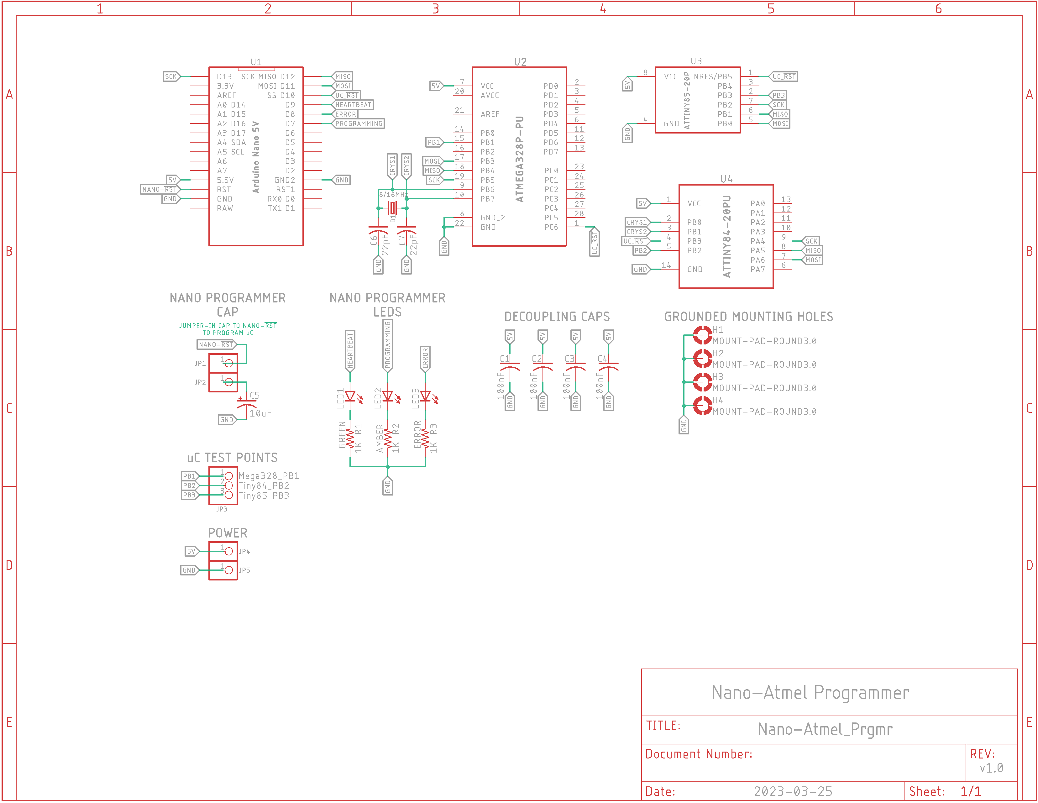
v1.0 Schematic
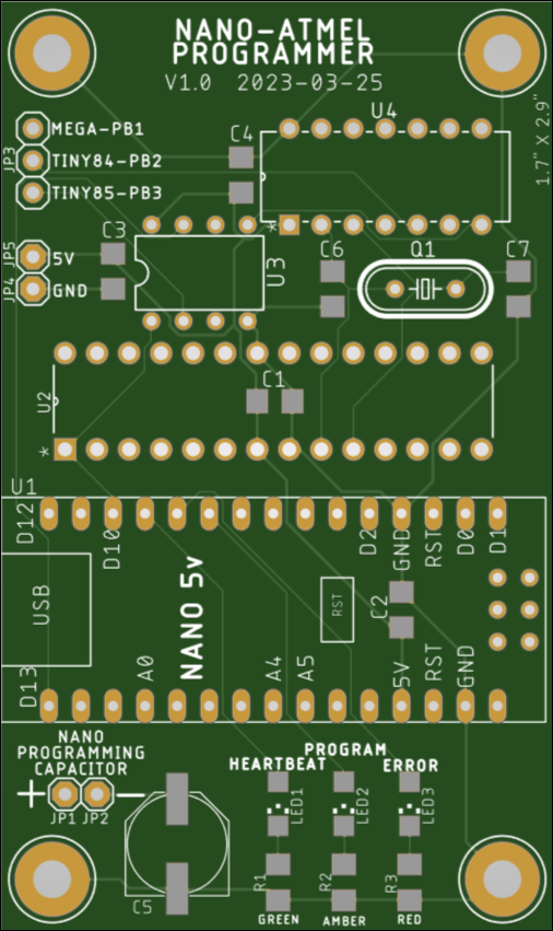
v1.0 Board Layout v1.0 PCB
Video: Programming ATtiny85 on a Breadboard (Click to enlarge)
The Nano is reset which causes all 3 LEDs (Heartbeat (green), Program (amber), Error (red)) to flash in rapid succession. At the 7-second marker the green and amber LEDs flash to indicate the code is being uploaded to the ATtiny85. Immediately afterwards the blue LED on the right side of the board starts flashing 5 times per second. This proves proper operation.
Video: Programming ATmega328P on the PCB (Click to enlarge)
In this video the Nano Reset button is pressed which causes the I.S.P. program to run and flash the LEDs.
The code in Clk_1MHz.ino is adjustable for mega328, tiny84 or tiny85.
The 'bare metal code' in ATtiny85_CTC_1MHz.ino is set for a 1MHz clock for an ATtiny85.
An ATtiny85 timer tutorial: generating time delay using interrupts.
|
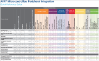
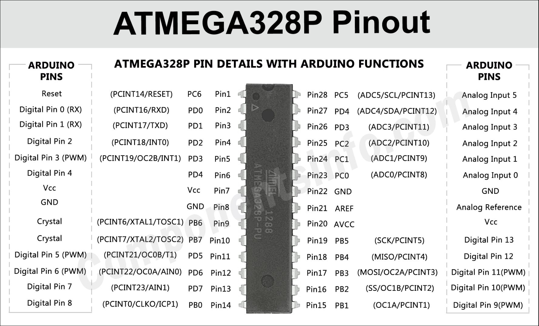
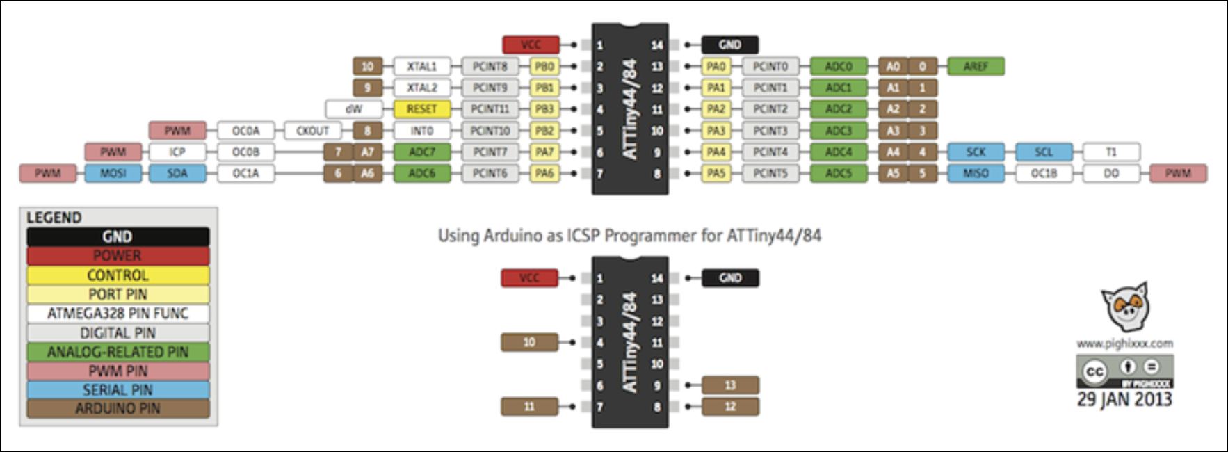
Description: An Arduino Nano is used as a programmer for 3 Atmel/Microchip devices: - ATMega328P (20-pin) - ATtiny84A (14-pin) - ATtiny85 (8-pin) AVR Features Comparison
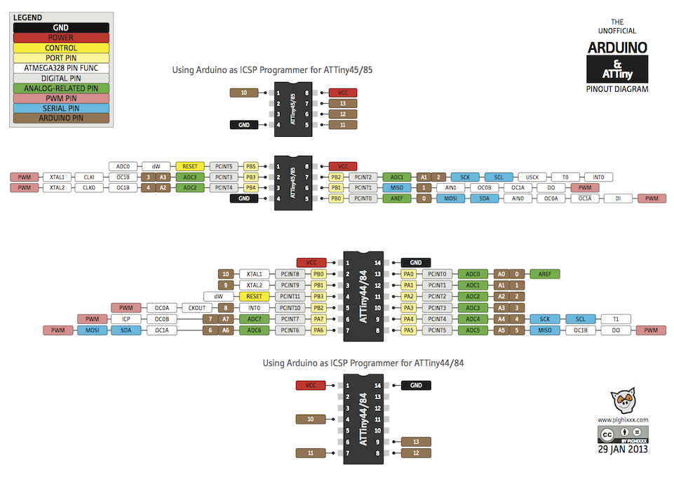
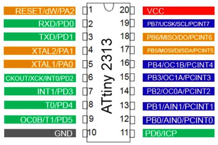
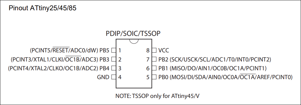
Pinout Diagrams: - ATtiny85 ATtiny Pinouts
Setting Up Your System: Follow the Programming Procedure below to configure the Arduino Nano (5v) as an ISP programmer using the default Tools | Programmer selection of "AVRISP mkII". Leave the 10uF electrolytic capacitor un-jumpered until the ArduinoISP sketch is loaded and running on the Nano. Then change the programmer to Tools | Programmer: "Arduino as ISP". Reset the Nano and you should see all 3 LEDs cycle: Heartbeat, Program and Error. Once it's ready to go - you'll know by the slow pulse on the green Heartbeat LED - jumper in the large cap to the Nano so it will not reset and try to run the program you're going to upload to the device. Change the Tools | Board selection to the chip/device you want to program, e.g., ATtiny Microcontrollers, ATtiny24/44/84, Processor ATtiny84, Clock Internal 8MHz, and the serial port the Nano is connected to. Use "<Shift> <Ctrl> U" (or hold down <Shift> while pressing the Upload button) to force the Nano to upload the code like Blink.ino to the target chip: ATMega328P, ATtiny84 or ATtiny85. You will hopefully only see Heartbeat and Program LEDs flash during the upload.
Programming Procedure: https://highlowtech.org/?p=1695
Note that if you are programming an ATMega328P, you'll need the breadboard board driver that can be found here or here.
How are the Atmel devices attached to the Nano programmer?
How do I test if the Atmel device is programmed? Run ATtiny85_CTC_1MHz.ino and attach an oscilloscope lead to a device test point on jumper JP3.
|
||||||||||||||||||||||||||||||||||||||||||||||||||||||||||||||||||||||||||||||||

![]()
![]()
Updated 2023-06-09 @ 10am
