![]()
| Program an ATtiny85 as a Squarewave Generator | |||||||||||||||||||||||||||||||||||
| Diagrams & Information | Registers |
Page |
|||||||||||||||||||||||||||||||||
|
We are trying to use a tiny85 to produce a square wave that we can use as a CPU clock.
There are a few different methods to generate time delay: timers, counters and interrupts. We are going to use the Clear Timer on Compare (CTC) mode of operation, also know as the Compare Match method.
Unlike the Arduino UNO R3 that has three I/O ports (Port B, Port C, Port D) that are up to 8 pins wide, the Atmel/Microchip ATtiny85 has only one 6-pin port, Port B.
PORTB is an 8-bit address register (only 6 of the 8 bits are available) found at memory location 0x18. Each port pin is uniquely named PORTB0 through PORTB5. The register that takes care of the data direction of each the port pins as either input (0) or output (1) is called DDRB. Each port pin can be uniquely identified by its name, e.g., PORTB1 is PINB1 (for input) and its direction is governed by DDB1. More info can be found on page 64+ of the ATtiny85 Datasheet.
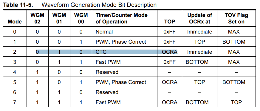
CTC mode requires the WGM0x bits in registers TCCR0B and TCCR0A to be set as highlighted in the table below.
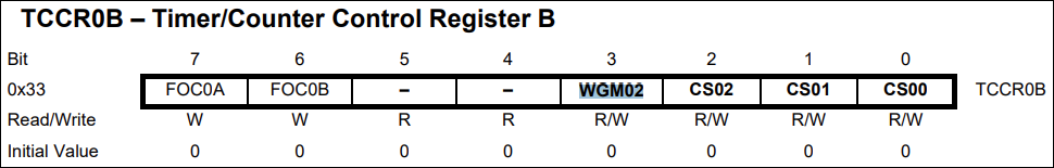
CTC mode requires WGM02, WGM01 and WGM00 bits to be set to 010. WGM02 is found in TCCR0B as bit 3.
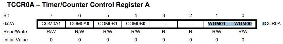
WGM01 and WGM00 are found in TCCR0A as bits 1 and 0.
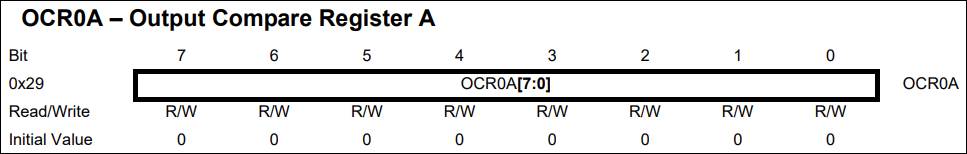
Once a mode like CTC is selected and the corresponding bits have been selected in the two control registers (TCCR0x), a count-to-value needs to be set in OCR0x. This is compared continually to TCNTx, the counting register, to see if the counts match.
NOTE: If you want to create a slow square wave signal like 1Hz, you will need a prescaler; for a fast one (1MHz) you won't.
Count-to-value is set in OCR0x. In CTC mode, TCNTx continually compares itself to this value to know if count is reached.
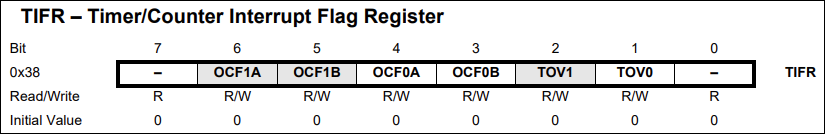
When the number of TCNT0 counts matches the value we set in OCR0A, the OCF0A flag bit in the TIFR register will be set. We can set the number of flags in a loop to deal with long prescaler values like 1024.
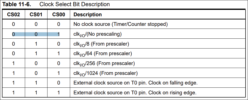
1Hz Signal Procedure: - Divide the chip clock frequency by the prescaler value chosen by the CS0x bits in the TCCR0B register (shown above). A slow signal (1Hz) means we need a large prescaler value: 1 / (16MHz / 1024 prescaler) = 1 / (16000000 / 1024) = 0.000 064s = 0.064ms. Each time the prescaler value of 1024 is reached, a step time of 0.064ms has elapsed - One second is 1000ms so we need to choose a step number that divides evenly into 1000ms, like 10ms. Then we divide this chosen time interval by the step time: 10ms / 0.064ms per step time = 156.25 steps that TCNT0 must see in order to equal 10ms. - 156 is the number of times that TCNTx will have counted to the prescaler value of 1024 to equal 10ms. This is the value OCR0x is looking for before it will trigger the OCF0A flag bit in the TIFR. We will put the value 156 into the OCR0x register. - When the number of TCNT0 counts matches the value of 156 that we set in OCR0A, the OCF0A flag bit in the TIFR register will be set. We will need a separate counter of the flag bits being reset to know when we have hit the desired frequency rate: a count of 100 x 10ms gives us the 1000ms or one-second timer we need for the 1Hz square wave signal.
1kHz Signal Procedure: - 1kHz is a slow signal requiring a large prescaler like 1024 - 1kHz = 0.001s = 1ms - Scaler = 1024. 1 / (16MHz / 1024) = 0.000 064s = 0.064ms step time - 1ms / 0.064ms per step = 15.625 steps; we will round down to 15. We will put *half* this value in OCR0x (OC0B [PB1] must be toggled twice to give us a cycle) - When TCNT0 = OCR0A value of 15/2, the OCF0A flag bit will fire in the TIFR register. We can put this in a loop looking for 1 flag bits before resetting the flag bit and toggling PB1. (In the 1Hz signal, the count was set to 100.)
1MHz Signal Procedure: The procedure for a 1MHz timer is a little different. When the square wave time is long, a bigger prescaler value is needed. When the square wave signal is short/fast like a 1MHz one, then the prescaler is not needed at all. - 1MHz = 1000KHz = 0.000 001s = 0.001ms - Scaler = NONE: 1 / (16MHz) = 0.000 000 0625 = 0.000 0625ms step time - 0.001ms / 0.0000625ms per step = 16 steps. We will put *half* this value in OCR0x. (OC0B [PB1] must be flipped twice to give us a clock cycle) - When TCNT0 = OCR0A value of 16/2, the OCF0A flag bit will fire in the TIFR register. We can put this in a loop looking for 1 flag bits before resetting the flag bit and toggling pin PB1
There are two 8-bit compare match registers, OCR0x that are used to compare with any timer counter register, TCNTx. When TCNT0 equals OCR0A (a count has been reached), the Output Compare Flag (OCR0A) will be set.
Table 10-3 on page 60 shows the various functions of each ATtiny85's pins. Pin PB0 supports Timer/Counter0 Output Compare match A whereas PB1 supports both OC0A and OC0B registers. Just as there are two counter compare registers, there are also two TCNTx registers. We will use pin OC0B, PB1 for our clock output with TCNT0.
Software Arduino 'bare metal' code to have ATtiny85 produce a 1Hz squarewave. Arduino 'bare metal' code to have ATtiny85 produce a 10Hz squarewave. Arduino 'bare metal' code to have ATtiny85 produce a 1kHz squarewave. Arduino 'bare metal' code to have ATtiny85 produce a 1MHz squarewave.
Reference: Intro to Bare-Metal Coding for Arduino |
TCNTx: Timer/Counter registers 0, 1.
TCNTx is continually compared to the value you set in OCR0x. Whenever TCNT0 equals OCR0x, the comparator signals a match. A match will set the Output Compare Flag (OCF0x) at the next timer clock cycle. We can use the number of flags to determine how many times to loop an action. This is what happens in the 1Hz square wave code. |
65, 69, 72, 80 | |||||||||||||||||||||||||||||||||
|
OCR0x: Output Compare Registers A & B We set this value as the number of steps that must be performed between OC0B (PB1) toggles. |
65, 69, 71, 78, 80
|
||||||||||||||||||||||||||||||||||
|
OC0A (PB0) and OC0B (PB1)
pins can be toggled, set or cleared so they are ideal for square
wave signal generation. The action is dependent upon the settings of COM0xy bits in TCCR0A. |
81, 82
78 |
||||||||||||||||||||||||||||||||||
|
TCCR0x: Timer/Counter Control Registers A & B. TCCR0A bits 4 to 7 determine if PB0 (OC0A) or PB1 (OC0B) will be disconnected, toggled/cleared/set on Compare Match. |
77 | ||||||||||||||||||||||||||||||||||
|
OCF0x: Output Compare Flags A &
B within TIFR Each time TCNT0 = OCR0x, the OCF0x flag will fire. We can use this to count the steps between OC0B(PB1) toggles. |
69, 81 | ||||||||||||||||||||||||||||||||||
|
TIFR: Timer Interrupt Flag Register Contains the OCF0x flags. |
81 | ||||||||||||||||||||||||||||||||||
|
|
|||||||||||||||||||||||||||||||||||
![]()
![]()
Updated 2023-05-01 @ 8am
