![]()
LEDs - 05
![]()
|
In this section we are going to: - Review how to set (1), clear (0), or toggle (0/1) all bits in a Port - Set a single bit in a port to 1 using OR. OR symbol used is "|" - Clear a single bit in a port to 0 using AND. AND symbol used is "&" - Toggle a single bin in a port using NOT - "Bit Manip: OR with 1 to set, AND with 0 to clear." |
||
|
OR Gate Examine the Truth Table on the right: when A or B is a 1, there is a 1 OUTput at Q in the OR Logic Gate on the left. OR symbol is "|". OR a bit with 0: the bit (0 or 1) remains the same. OR a bit with 1: the bit (0 or 1) becomes a 1. This is how we set a bit. |
|
 |
|
AND Gate Examine the Truth Table on the right: when both A and B are a 1, there is a 1 OUTput at Q in the OR Logic Gate on the left. AND symbol is "&". AND a bit with 1: the bit (0 or 1) remains the same. AND a bit with 0: the bit becomes a 0. This is how we clear a bit. |
|
 |
|
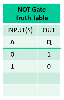
NOT Gate Examine the Truth Table on the right: if A is 1 then OUTput is 0. If A is 0, then OUTput is 1. Also known as an inverter gate. NOT symbol is "~". NOT a port of 8 bits: 0000 0001 becomes 1111 1110. 0x01 becomes 0xFE. NOT is used to toggle a bit. |
|
 |
|
Exclusive-OR (EXOR) Gate Examine the Truth Table on the right: if either A or B but not both is a 1, then OUTput is 1. EXOR symbol is "^" EXOR a 0 or 1 bit with 0: the Port bit remains the same. EXOR a 1 bit with 1: the Port bit becomes a 0. EXORing any bit with a 1 will toggle it (0 becomes 1, 1 becomes 0). In hardware design, the X-OR gate can be used to merge clock and data together into a single datastream. |
 |
 |


![]()
![]()
![]()