|
ZB64EC-bus Powered Six-slot Backplane |
| PCB Circuit (click to enlarge) | Circuits & Info |
|
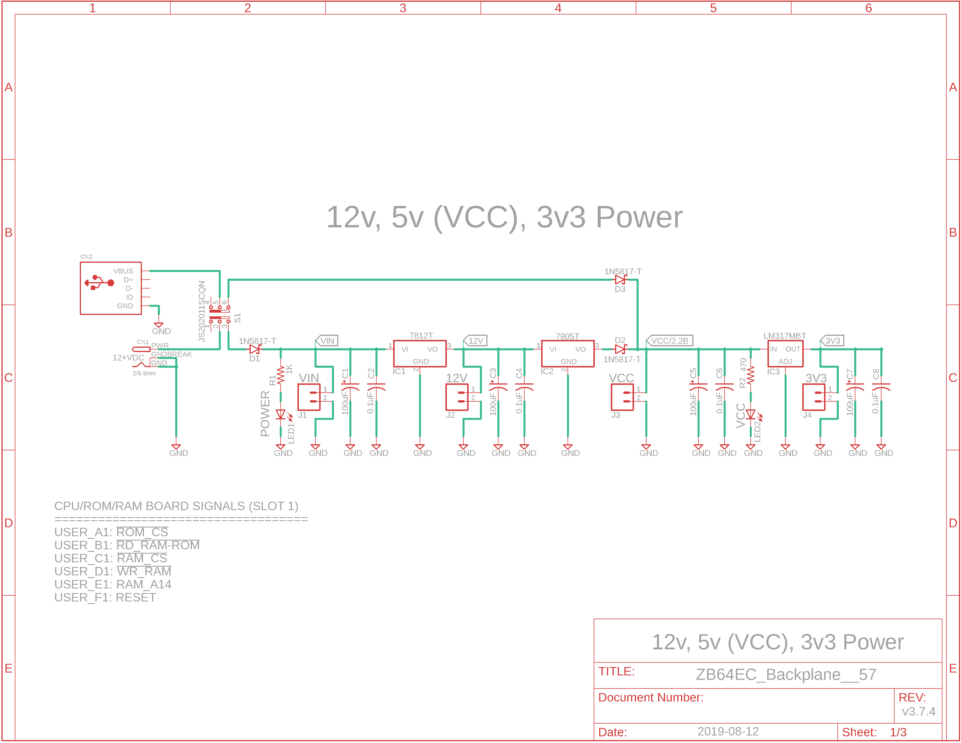
Eagle CAD: 0. Backplane Power Supply
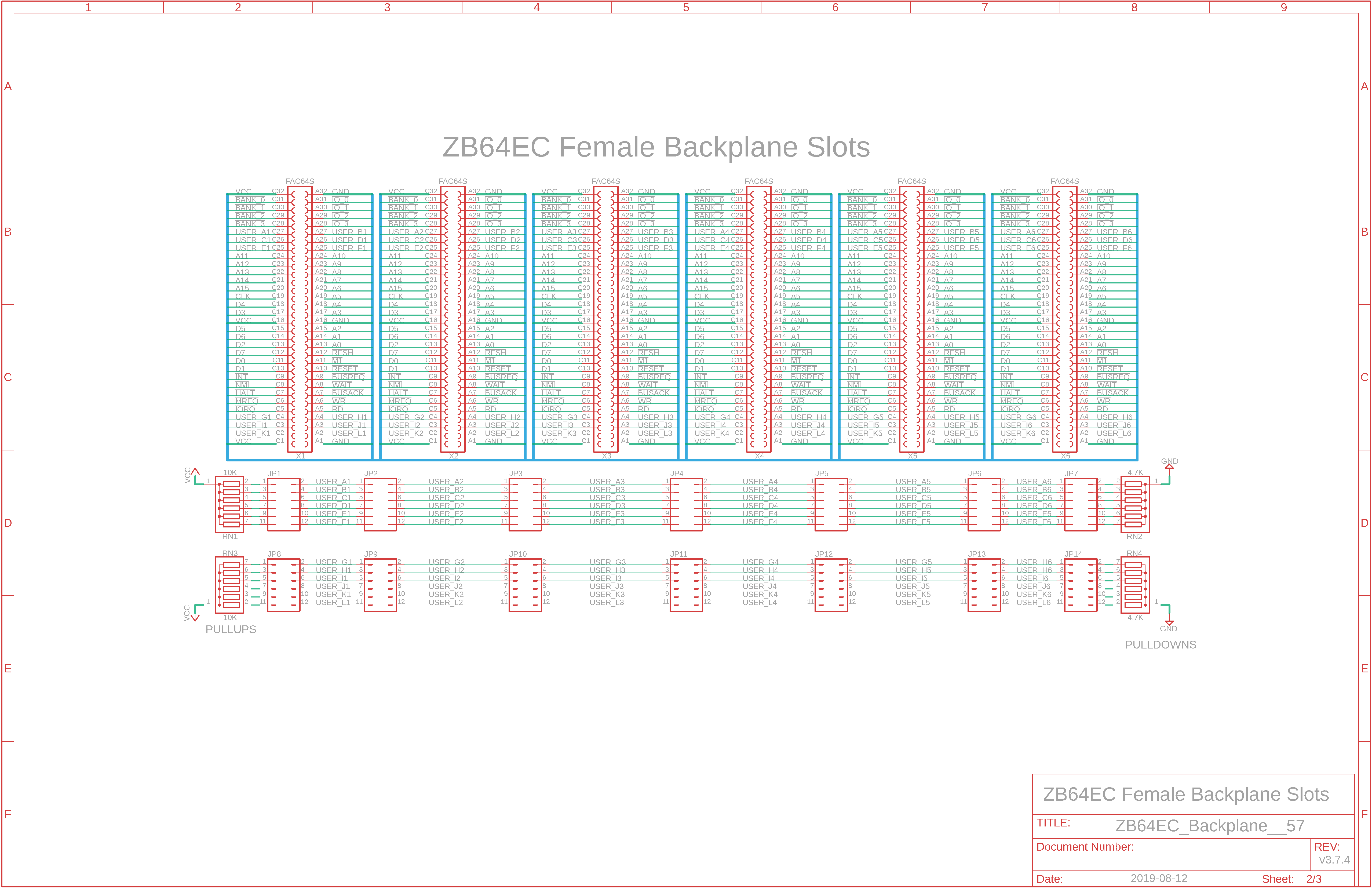
Eagle CAD: 1. Backplane Slots
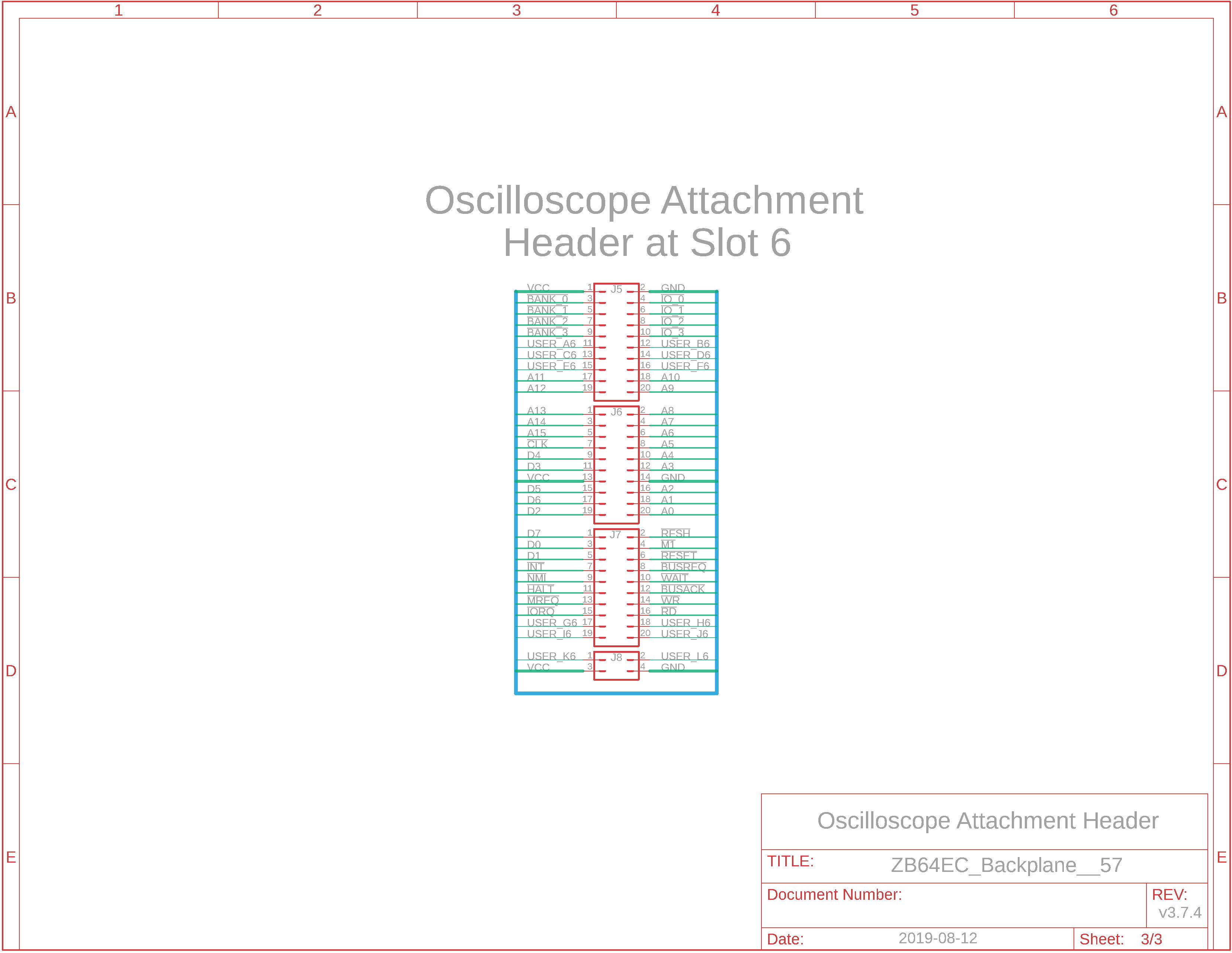
Eagle CAD: 2. Oscilloscope Attachment Interface / Backplane Extension Interface
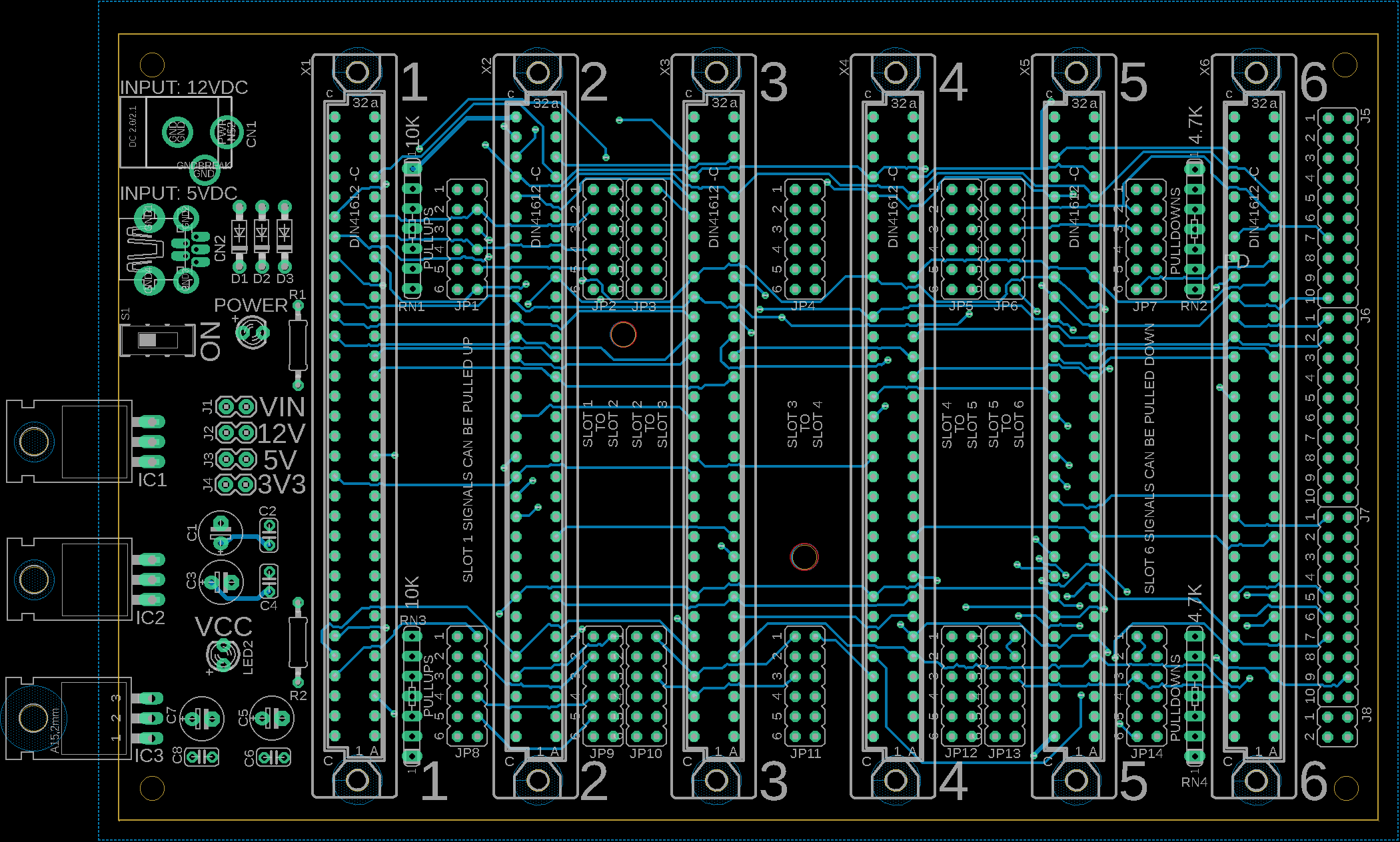
Eagle CAD: 3. A Possible PCB Layout
(Bill of Materials) |
Overview The backplane is a simple design. It uses a 2.5mm barrel connector/power jack to: - power the 12v regulator which... - powers the 5v regulator for VCC which... - powers the 3.3v regulator. The power is available only via jumper JP4
How many cards can I put in the backplane? Six. The first three comprise the multi-board Z80 computer and will include: - CPU/ROM/RAM bd. - Bank 0 ROM/RAM switch bd. - UART comm bd.
Backplane Features 1) Essential Z80 system functions have been distributed over three 4" wide x 3" high (102 x 76mm) boards that fit into the first three slots of the 4" x 6" backplane. 2) 12 user bus lines, USER_A to USER_L, have been added for customization. These are in addition to the BANK_0 to BANK_3 and IO_0 to IO_3 bus lines created by Peter Murray of 39k.ca for his M62-bus based Z80 SBC. Each USER_x bus line can be terminated high (10K) or low (4.7K) or not at all. 3) Each USER_x bus line is available at each slot via jumpers. It is possible to use a single bus line across the backplane many times for different functions. See the adjacent Eagle CAD: 1. Backplane Slots to see how the slots can be interconnected as well as terminated, if needed. 4) The Oscilloscope Attachment Interface is also the connector used to add the multi-slot backplane extension. 5) You can design your own boards to add them to the system, and use any of the available bus lines or bus line sections if needed.
I see the schematics. Where is the Bill of Materials parts list? The BOM is at the bottom of the adjacent panel.
How big is the BP and what will the printed circuit board look like? The Powered Multi-slot Backplane PCB measures 100mm x 160mm (4" x 6"). Click the adjacent thumbnail to see a possible parts layout.
Note: M62 Bus is copyrighted by Peter Murray of Murray Electronics, http://www.39k.ca |
![]()