|
ZB64EC-bus Z80 CPU Board |
| PCB Circuit (click to enlarge) | Circuits and Info |
|
The ZB64EC-bus Z80 is a multi-board modular system; it is not a single board computer like the M62-bus and ZB64PC-bus based systems. |
|
|
Eagle CAD: 1. CPU/ROM/RAM Board
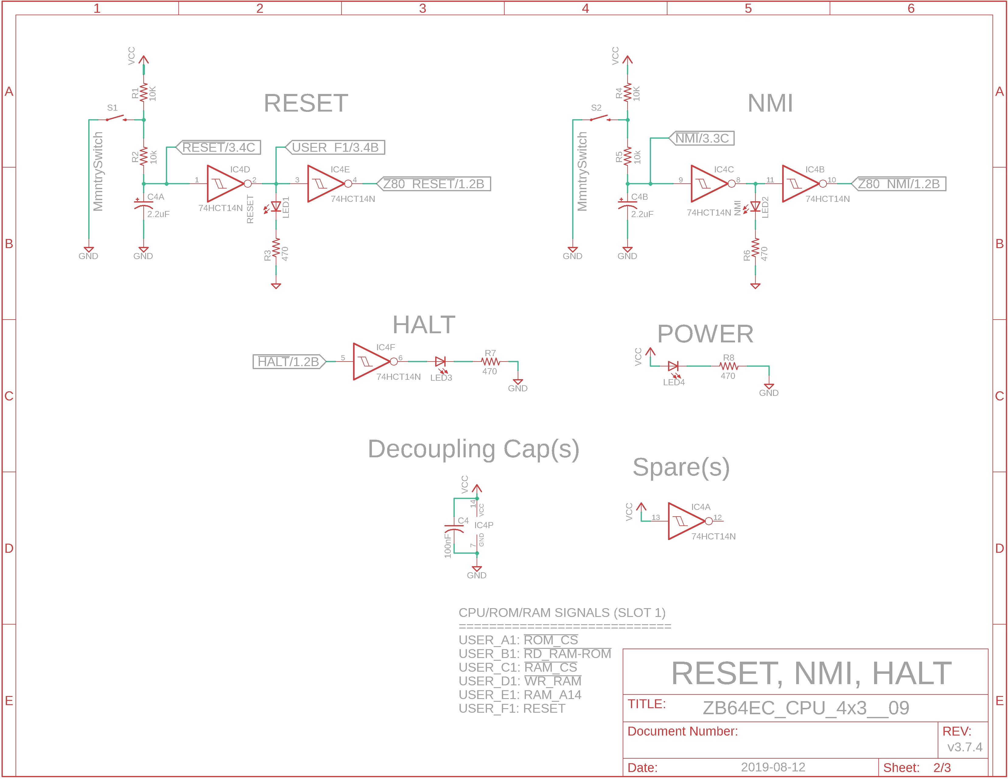
Eagle CAD 2: Reset, NMI, Halt Circuits
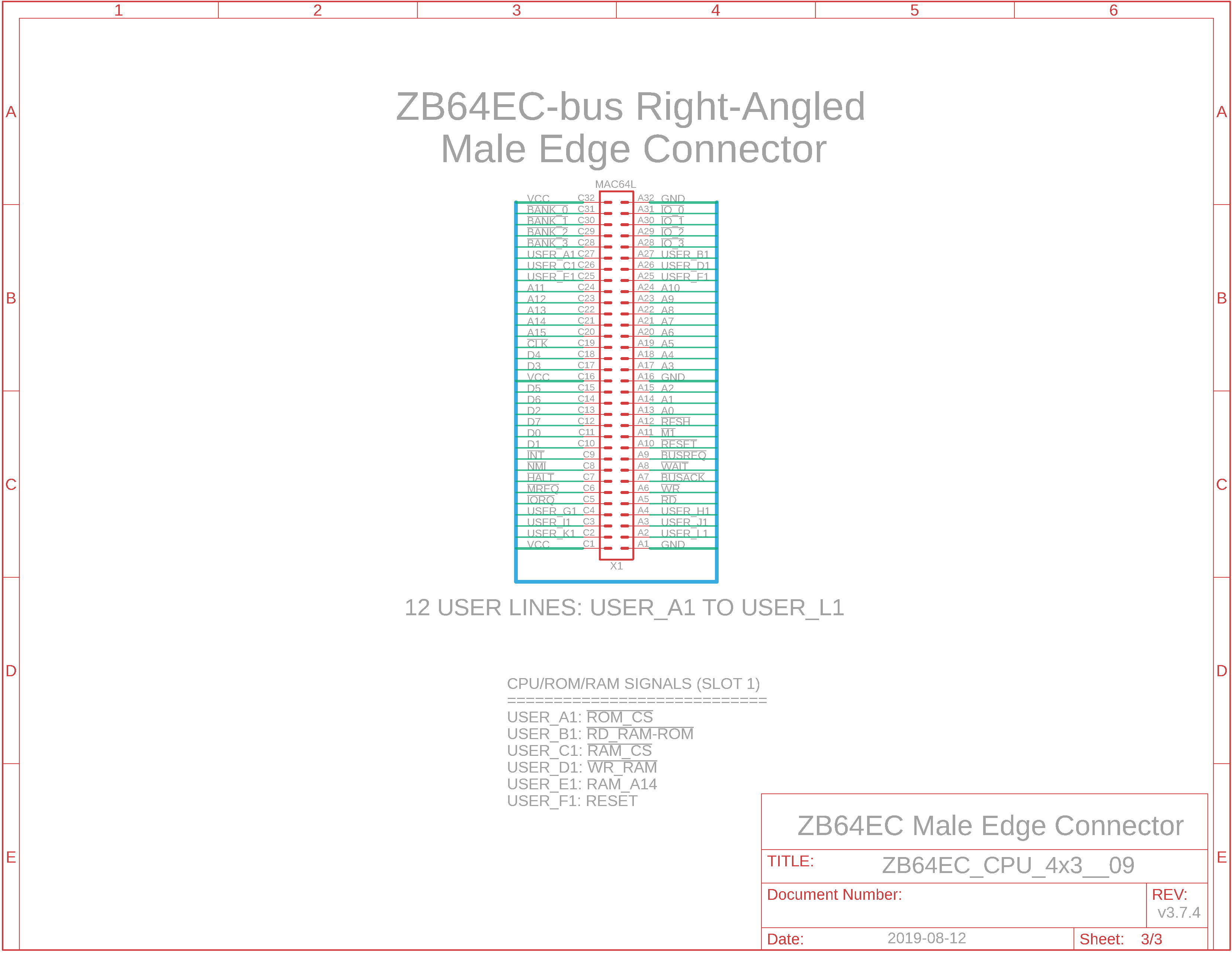
Eagle CAD 3: Right-angle Male Bus Connector
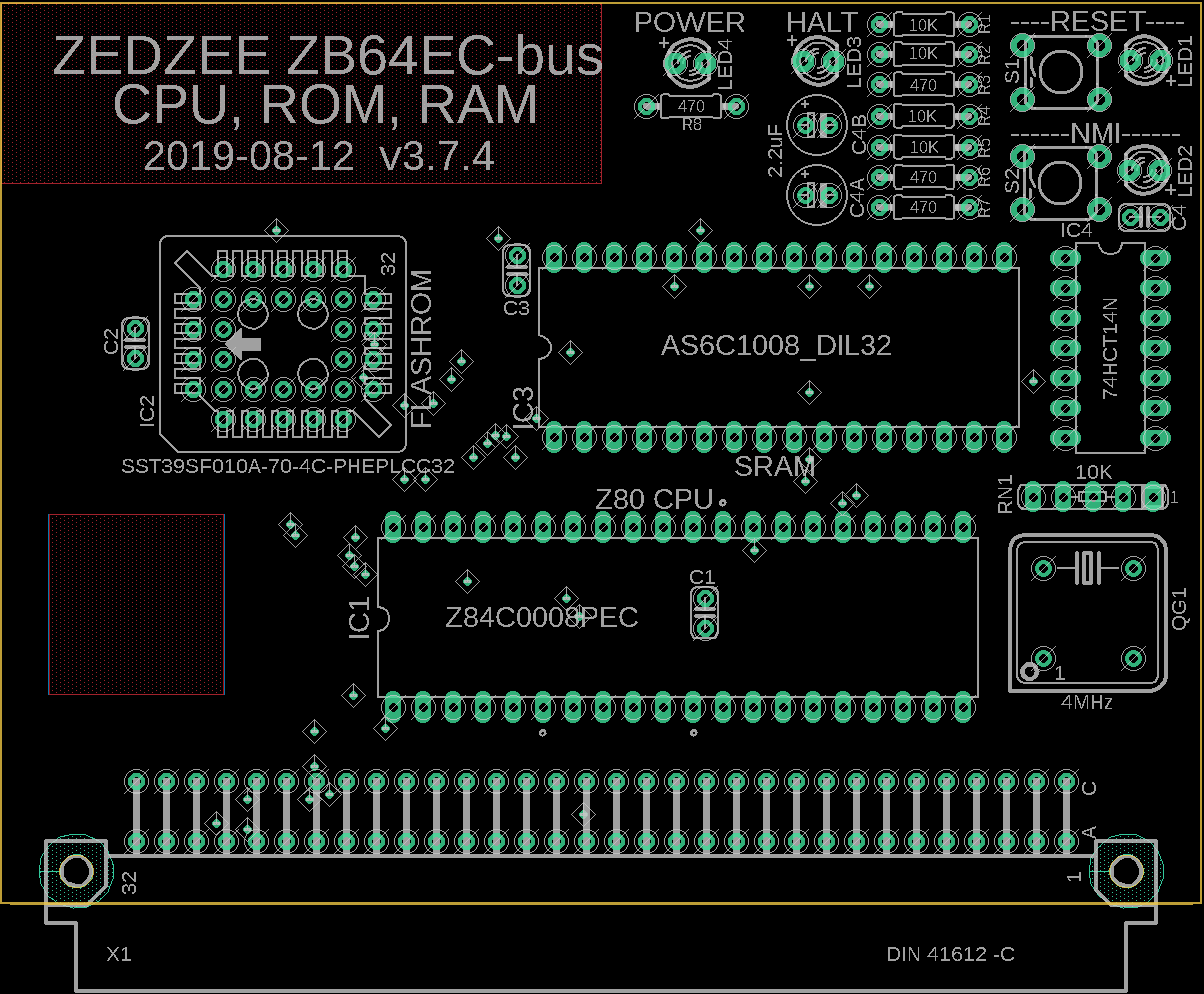
Eagle CAD 4: A Possible PCB Layout
Bill of Materials |
System Overview The ZB64EC basic Z80 system is modular and is composed of 4 boards: - an extendable 6-slot backplane - a CPU/ROM/RAM board - a Bank0 ROM-RAM switch board - a UART board for terminal communication
Additional boards can be added to the system, including a bus extension board. See the ZB64EC-bus Z80 MBC menu for the current list.
ZB64EC Z80 System Features 1) Essential system functions have been distributed over 3 boards. The boards are 4" wide x 3" high (102 x 76mm). This makes for easier troubleshooting as well as learning how the system and bus communication works. 2) 12 user bus lines, USER_A to USER_L, have been added for customization. These are in addition to the BANK_0 to BANK_3 and IO_0 to IO_3 bus lines created by Peter Murray of 39k.ca for his M62-bus based Z80 SBC. Each USER_x bus line can be terminated high (10K) or low (4.7K) or not at all. 3) Each bus line is available at each slot via jumpers. It is possible to use a single bus line completely across the backplane, or it can be used many times for different functions by only jumpering the needed bus sections. 4) You can design your own boards to add them to the system, and use any of the available bus lines or bus line sections.
Minimalist Design? Only the essential functions are designed into each board. The RESET circuit used by the Z80 needs to be inverted and carried over the bus to the RESET input of the UART. We see that as bus line USER_F1 in the Reset section of Eagle CAD 2: Reset, NMI, Halt Circuits It's listed at the bottom of the schematic.
I see the schematics. Where is the Bill of Materials parts list? The BOM is at the bottom of the adjacent panel.
How big is the ZB64EC Z80 CPU board and what will the printed circuit boards look like? The ZB64EC CPU board measures 100mm x 76mm (4" x 3"). Click on the adjacent thumbnail below to see a possible parts layout for your design for the CPU/ROM/RAM board.
Note: M62 Bus is copyrighted by Peter Murray of Murray Electronics, http://www.39k.ca |
|
|
|

![]()