|
Troubleshooting your ZB64PC CPU Board |
| Symptom | Action |
|
LED 5 not illuminated |
Ensure the USB power cable is firmly plugged into CN2 miniUSB connector on left side of board. Is JP5 jumpered? |
|
TeraTerm won't respond |
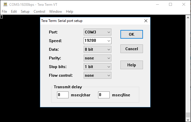
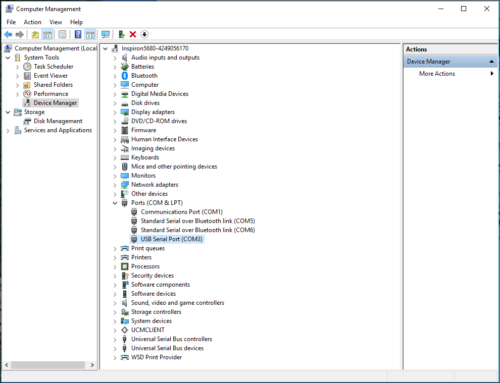
1) Set the jumper on the FTDI module to 5v and then plug it into SV1, the FTDI receptacle. Make sure the Bluetooth module is not plugged into SV2. 2) Check TeraTerm settings of 19200, 8, N, 1 under Setup | Serial Port. Which Port is in use? 3) Right-click This PC on your Win10 desktop, click Manage, click Device Manager, and click Ports (COM & LPT). Does a new port appear when you plug in the FTDI module? If so, is this the same port configured in TeraTerm? |
|
You suspect power may be an issue |
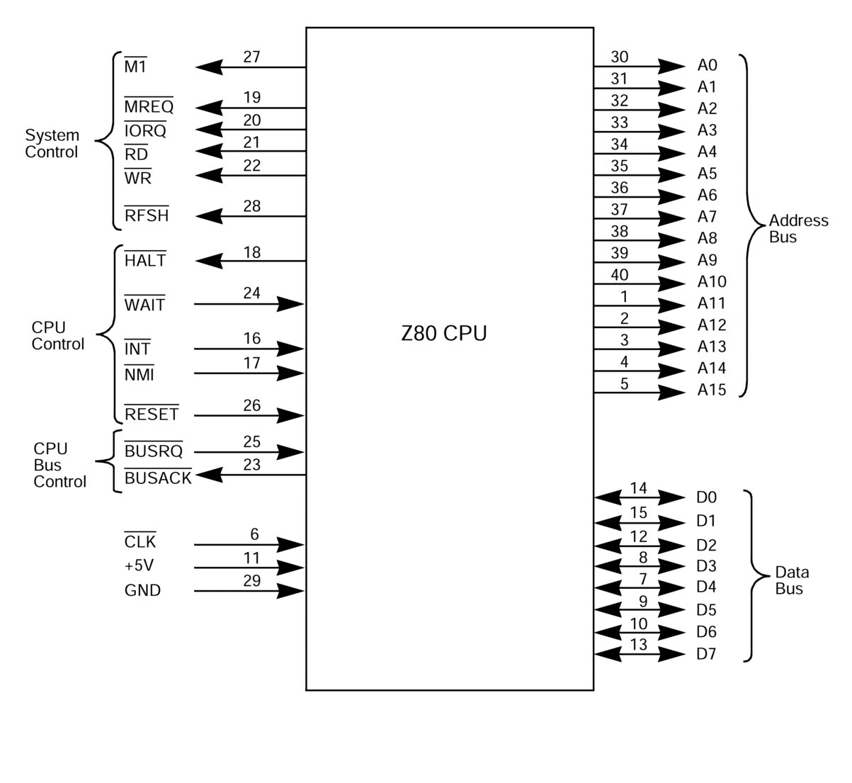
1) The ZB64PC's maximum current draw can be measured with the MAX232 chip removed and the FTDI serial module plugged in. (The Bluetooth over USB should not be plugged in, as you guessed.) The max current is typically less than 100mA. Here's a video showing one of several USB safety testers in use. 2) Check for a clean (no noise) clock on pin 6 of the Z80. 3) Check for clean power on pin 11 and clean ground on pin 29 of the Z80. If either is missing or messed up, follow the connections to the bus connector. 4) Use a multimeter to test for 5v on the power pin of every chip. Equally importantly, look for floating grounds on the ground pin of every chip. |
| You wonder if a pushbutton circuit is compromised |
1)Check that the HALT, NMI and RESET LEDs are extinguished. Press the RESET switch to see if the RESET LED illuminates. 2) All three circuits should be pulled high by default; use your scope to verify. |
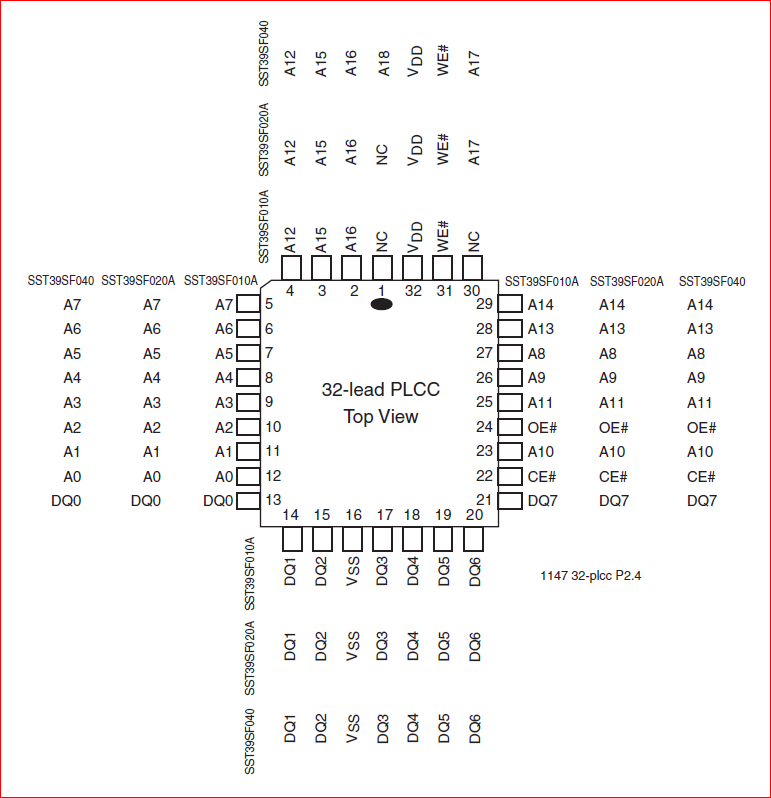
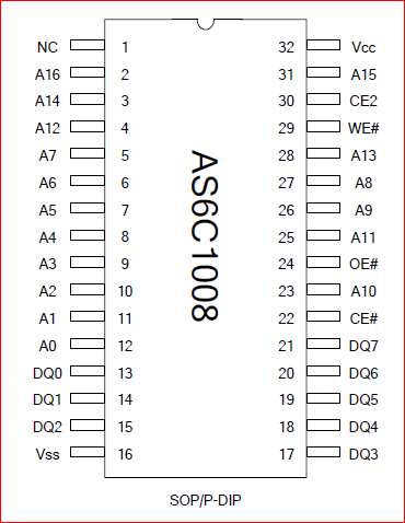
| You suspect a device is not being selected | 1) Check the low-active CS (chip select) pins of the ROM (pin 22), RAM (pin 22), UART (pin 16), etc. |
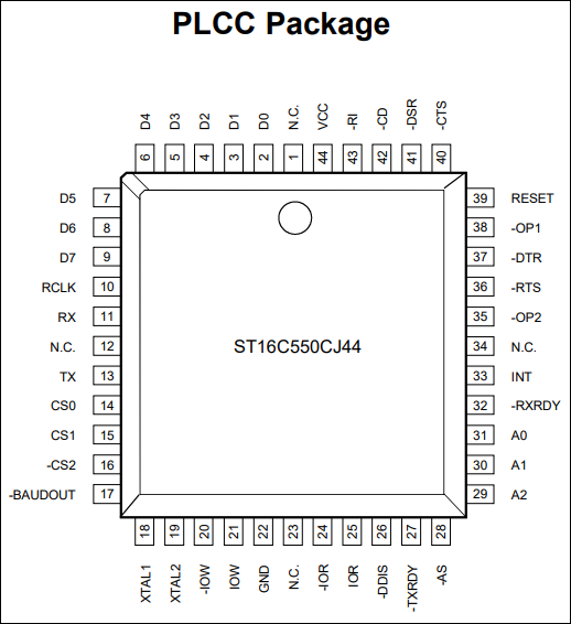
| You wonder if the UART is working | 1) If the ROM BIOS program is running, it's looking for UART input for the BIOS commands. That means we should see active signals on A0-A2; use your scope to examine pins 31 to 29 of the Exar ST16C550CJ PLCC44 UART chip; here's the pinout. |
| Primary ICs | T/S Info |
|
CPU Z80C00xx DIP40 Pinout Diagram
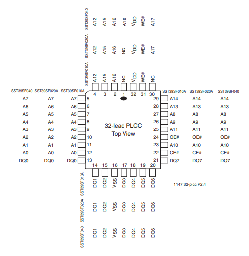
FlashROM SST39SF010A PLCC32 Pinout Diagram
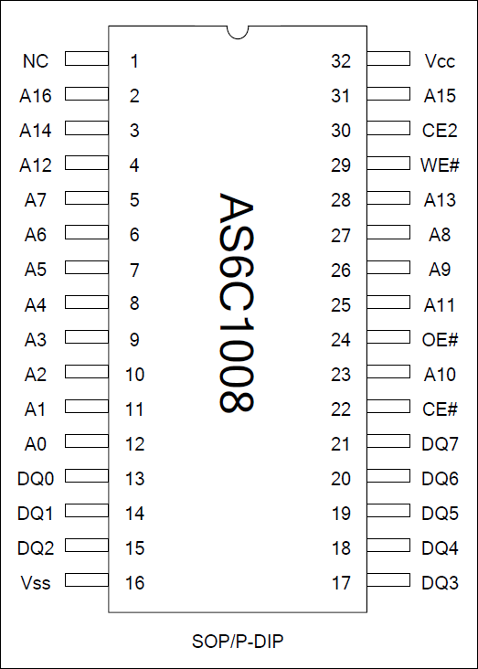
SRAM AS6C1008 PDIP Pinout Diagram
UART 16c550 PLCC44 Pinout Diagram
|
When troubleshooting the system buses (address, data, control), sometimes it's handy to have the pinouts of the major devices at the ready. Eyes left...
If you're not getting proper signal levels or number of transitions for a system bus signal like A0 or D0, try depowering the SBC, removing all of the major ICs including the CPU, then repowering the SBC. - Check CPU socket pin 29 for GND, pin 11 for 5V, and pin 6 for a 4MHz signal. - On my most recent (v3.7.2) board build from China, I did not reroute one of the "loose" (unrouted) GND airwires to the Z80 CPU. The result was an oddly pulsing chaotic signal on the CPU GND pin. ground. Running a patch wire from CPU pin 29 GND to the 4MHz crystal oscillator pin 4 GND fixed that problem.
Power off, add Z80 CPU, power on. Check A0 (pin 30) and D0 (pin 14). The CPU's Program Counter will advance through the addresses so you should see transitions on A0. Transitions on D0 will occur if you have the ROM installed. You need good clean signals.
|

![]()