|
ZB64PC-bus System Buses Monitor Board |
| PCB Circuit (click to enlarge) | Circuits and Info |
|
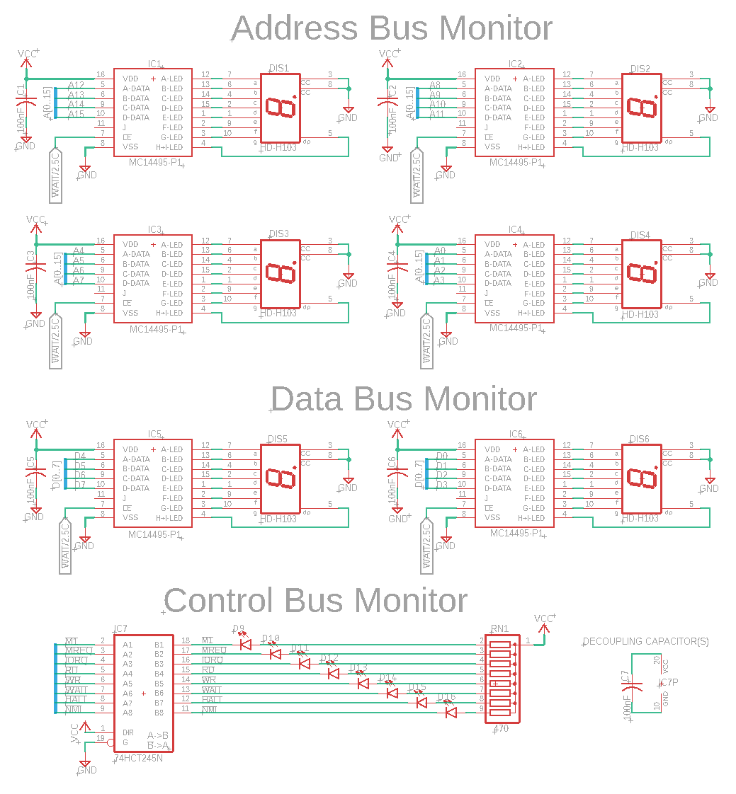
Eagle CAD: 1. System Buses Monitors
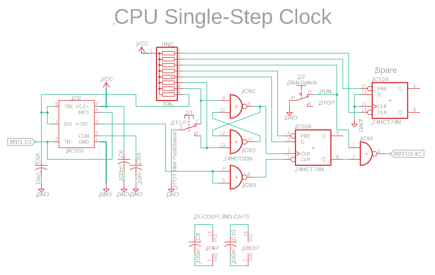
Eagle CAD: 2. CPU Single-Step
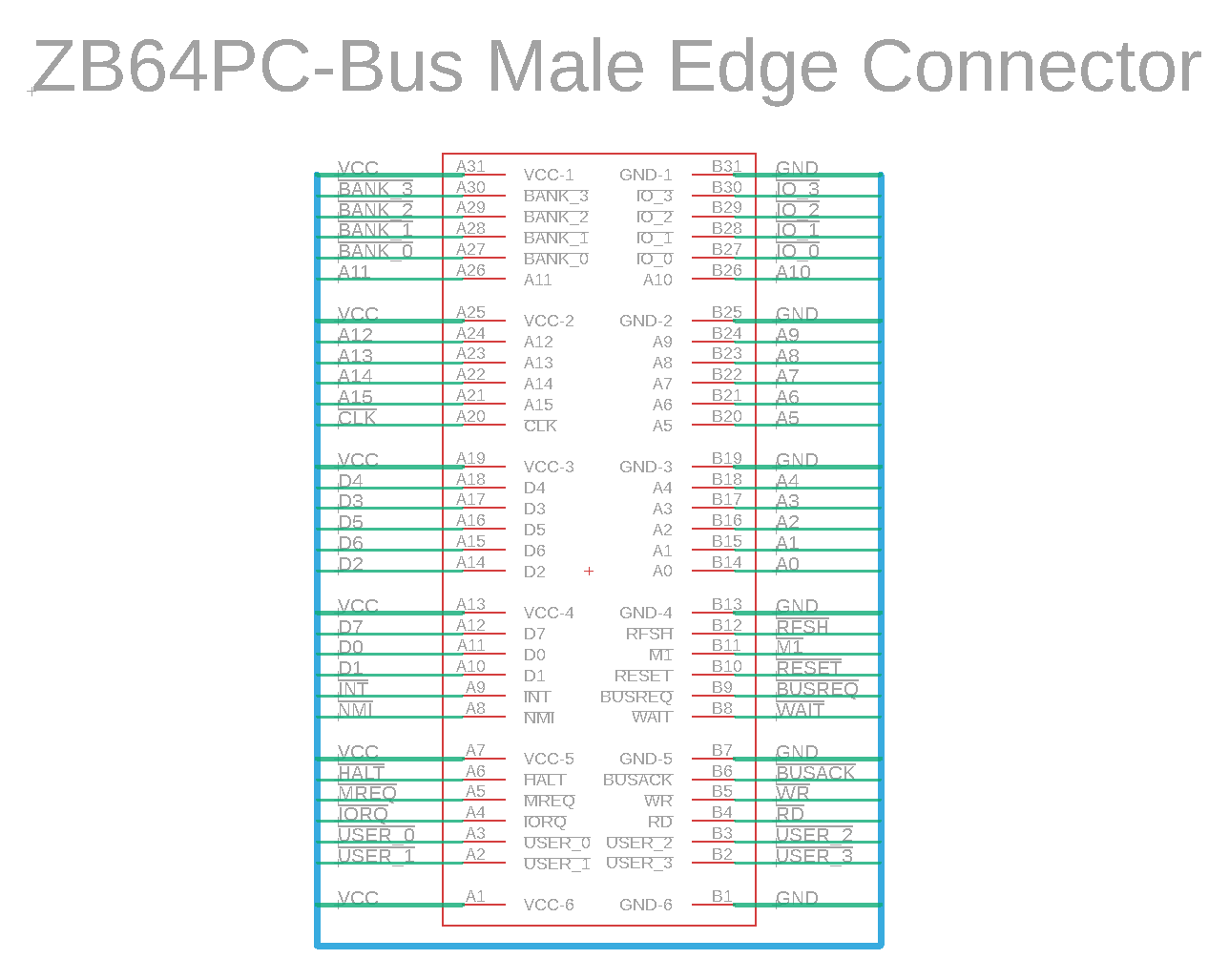
Eagle CAD: 3. ZB64PC-Bus Male Edge Connector
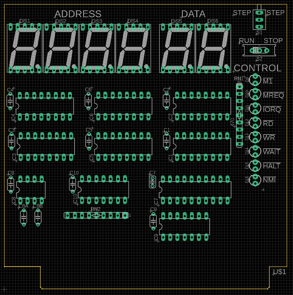
Eagle CAD: 4. A Possible PCB Layout
(Bill of Materials)
|
PLEASE NOTE: I do not sell production boards. If you would like to buy an M62 Z80 system board/parts kit, contact Peter Murray, Peter@39k.ca I simply provide you with information to build your own breadboard computer.
Overview The ZB64PC Bus Monitor board can only be used with the ZB64PC-bus SBC board and backplane.
Operation There are 6 MC14495 chips that convert 4 binary signals to their hex equivalent. As an example, hex value F we know to be 1111 in binary. By hooking up 4 of them to the 4-bit groupings that make up the 16-bit address bus, we can monitor the current values on said bus. The same is true for the 8-bit data bus but we'll only need 2 chips. The LEDs are common cathode units as you guessed because their common feeds on pins 3 and 8 are connected to ground. The Control Bus uses a '245 driver to connect all of the Z80 control signals to LEDs without loading down the current-loading-sensitive Z80 bus. The CPU Single-Step circuitry uses a 555 timer to fire the NAND latch, IC9, sequentially without keybounce from the STEP switch, S1. When M1 fires with each new instruction, pressing the STEP button fires the WAIT input signal to the Z80. While waiting, it simply runs NOPs. Please keep in mind that you may only see the beginning of each new instruction, its first operand, due to the way WAIT works. If you need more, consider and ICE.
I see the schematics. Where is the Bill of Materials parts list? The BOM is at the bottom of the adjacent panel.
How big is the SysBusMonBd and what will the printed circuit board look like? The PCB measures 100mm x 100mm (4" x 4"). Click the adjacent thumbnail to see a possible parts layout.
Note: M62 Bus is copyrighted by Peter Murray of Murray Electronics, http://www.39k.ca |
![]()