|
ZB74-bus Backplane |
| PCB Circuit (click to enlarge) | Circuits & Info |
|
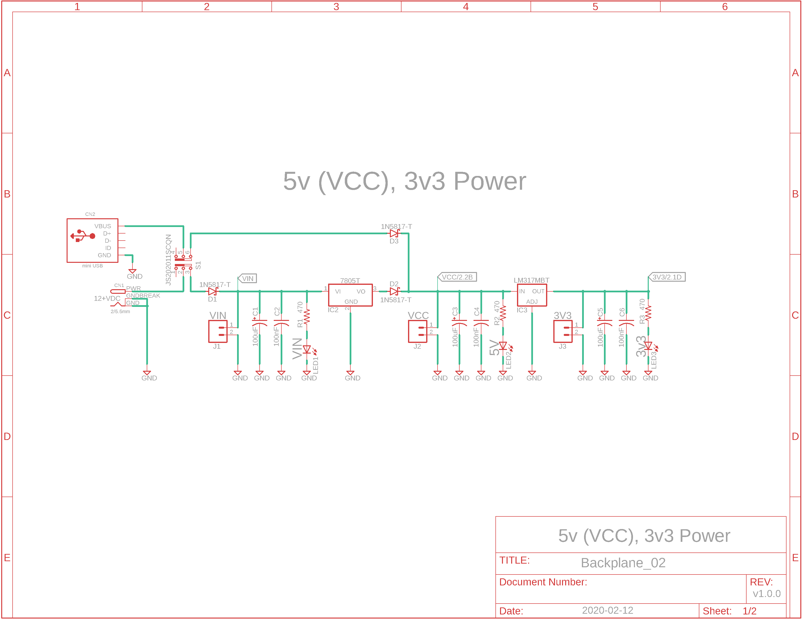
Eagle CAD: 0. Backplane Power Supply
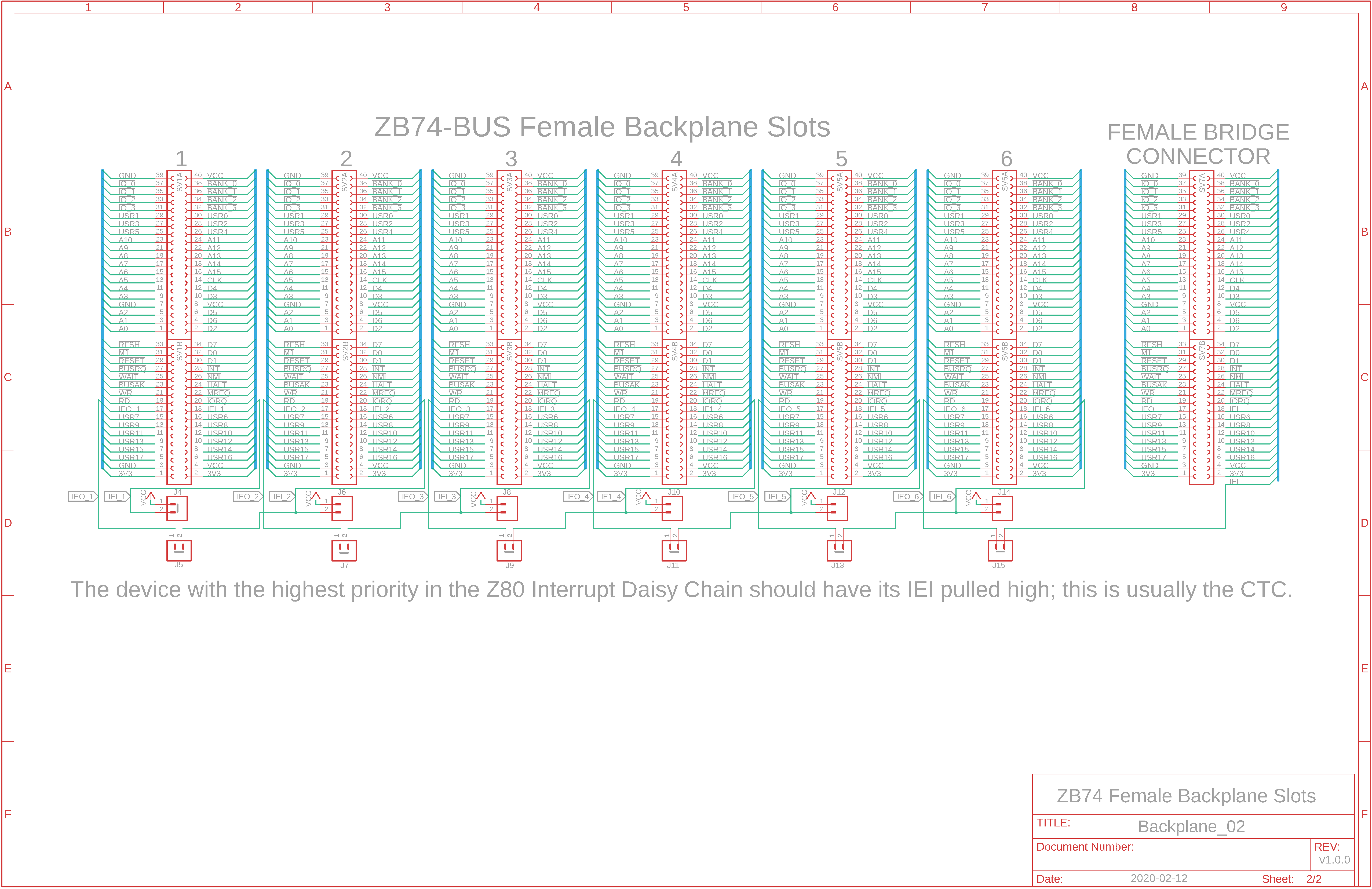
Eagle CAD: 1. Backplane Slots
Eagle CAD: 2. A Possible PCB Layout
(Bill of Materials) |
Overview The backplane is a simple design that provides both 5v and 3v3 DC from either of two power sources: - 2.5mm barrel connector/power jack for 7.5v to 20vDC input - miniUSB
How many cards can I put in the backplane? There are six female slots. You will need both the CPU board and the UART comm board if you wish to use a terminal emulator on your host PC: - CPU/ROM/RAM bd. with addressing circuitry for 512KB FlashROM and 512KB SRAM - Z80 SIO/2 UART serial communications bd.
Backplane Features First two boards listed above need to be installed into the backplane as a minimal system. 1) Z80 daisy chain system utilizing Interrupt Enable In (IEI) and Out (IEO) has been implemented. Only a non-CPU board that needs to be the lead in the daisy chain requires its IEI to be pulled high with a jumper. If you place the CPU board in slot 1 and the SIO/2 UART Comm board in slot 2, then you'll probably place the CTC board in slot 3. Pull up its IEI to VCC with jumper JP8 so that its interrupts are handled in a timely fashion. 2) 18 user bus lines, USR0 to USR17 have been added for customization. These are in addition to the BANK_0 to BANK_3 and IO_0 to IO_3 bus lines created by Peter Murray of 39k.ca for his M62-bus based Z80 SBC. USR lines currently in use: USR0: CTC CLK1 USR1: CTC CLK2 USR2: CTC CLK3 USR3: RESET USR4: INT USR5: 1843200 CLK 3) You can design your own boards to add them to the system and use any of the available USR lines if needed.
I see the schematics. Where is the Bill of Materials parts list? The BOM is at the bottom of the adjacent panel.
How big is the BP and what will the printed circuit board look like? The Powered Multi-slot Backplane PCB measures 100mm x 160mm (4" x 6"). Click the adjacent thumbnail to see a possible parts layout.
Note: M62 Bus is copyrighted by Peter Murray of Murray Electronics, http://www.39k.ca |

![]()