|
ZB74-bus Counter/Timer Circuit (CTC) Board |
| PCB Circuits (click to enlarge) | Circuits and Info |
|
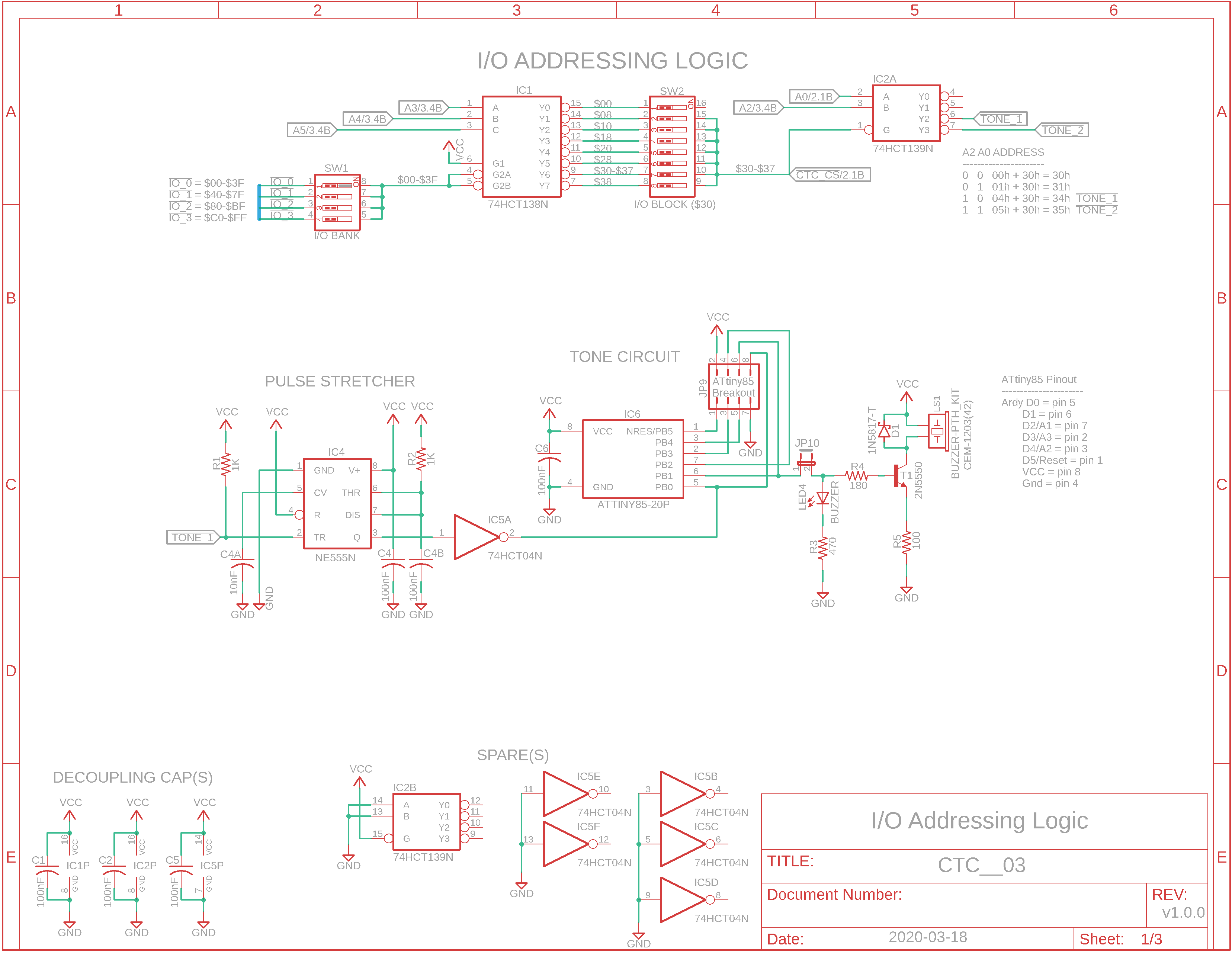
Eagle CAD 1: Address Logic
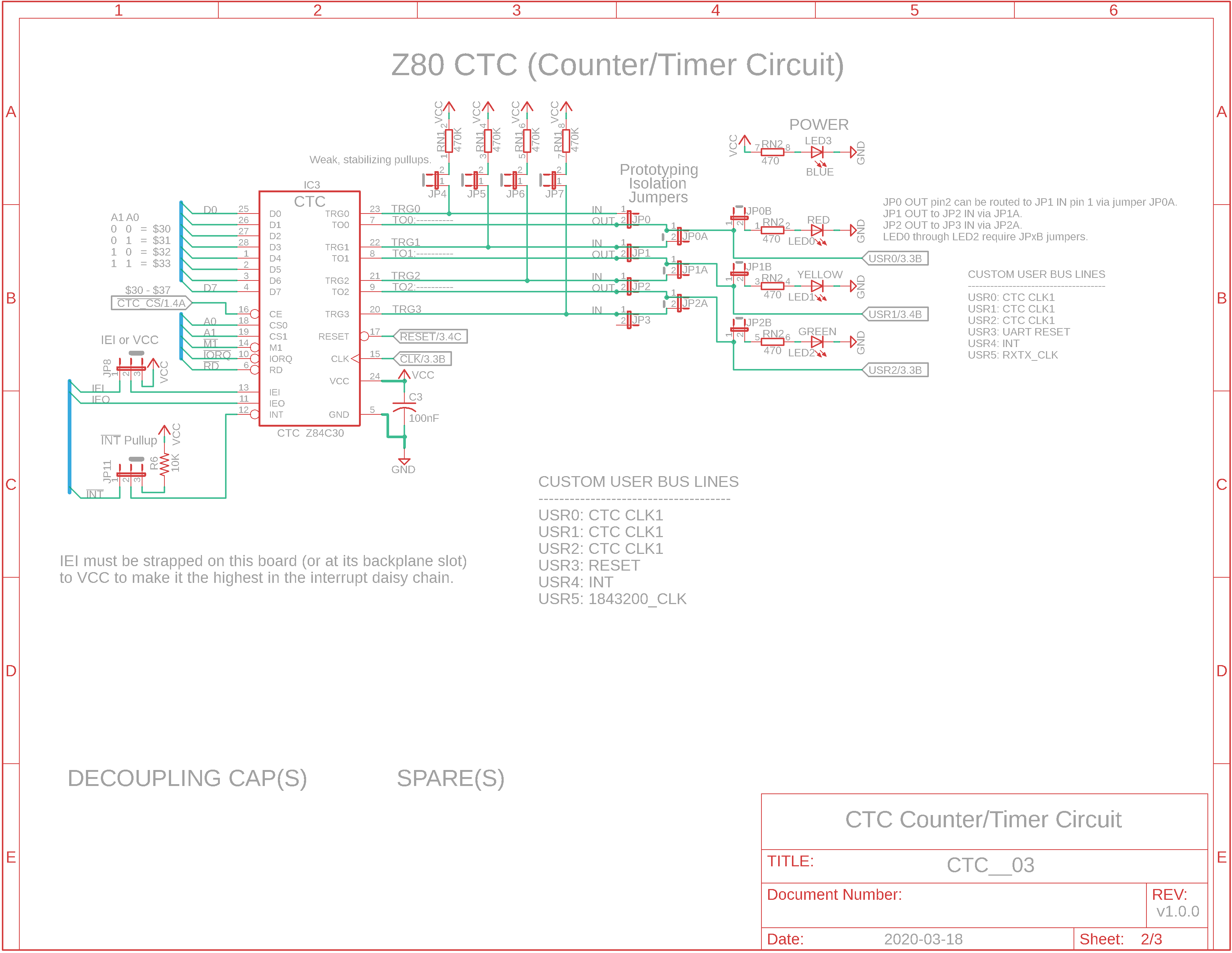
Eagle CAD 2: CTC
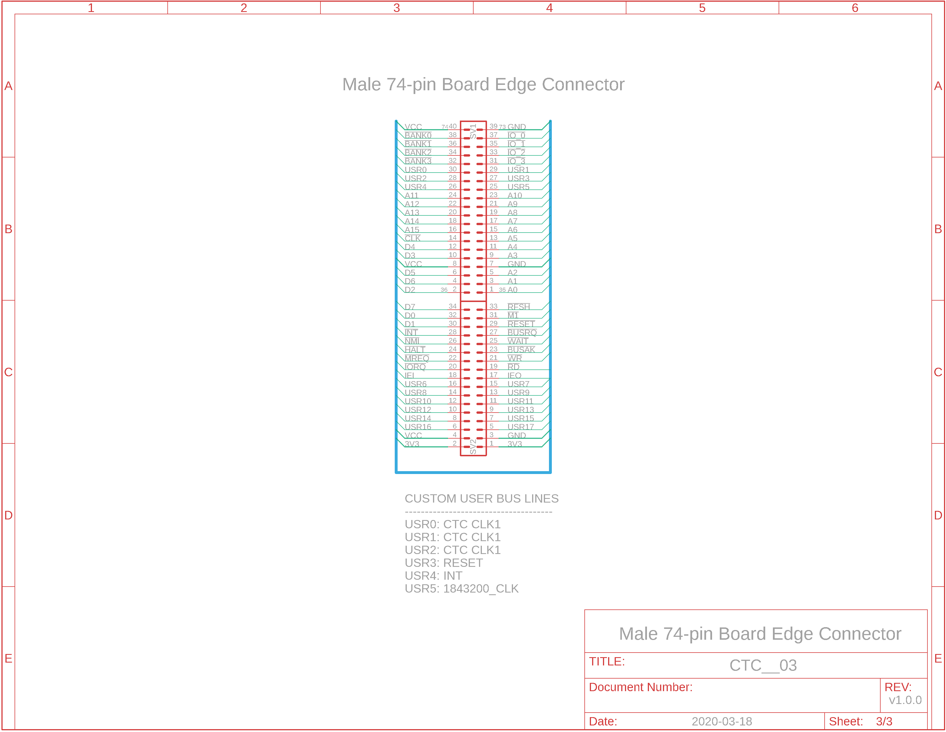
Eagle CAD 3: 74-pin Board Edge Connector
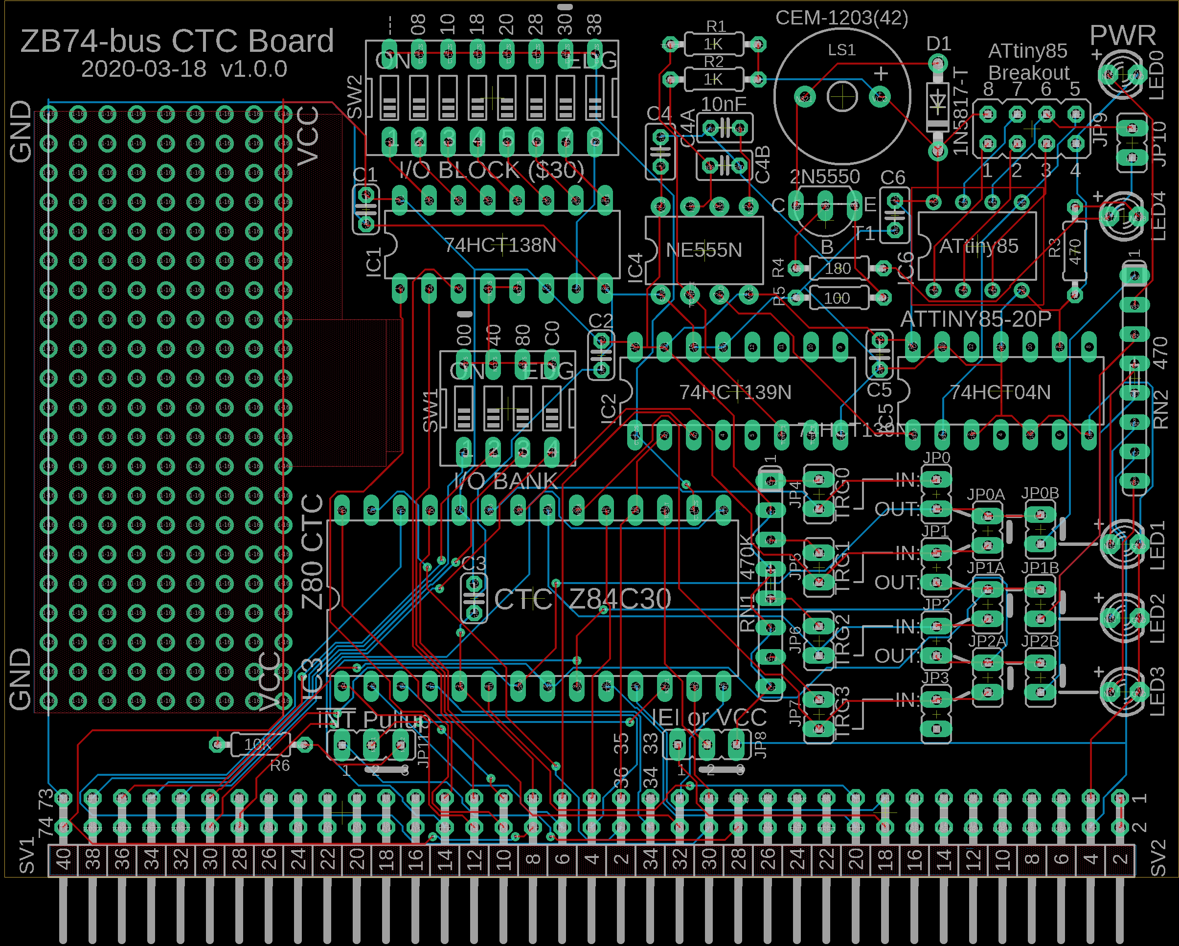
Eagle CAD 4: Possible PCB Layout
(Bill of Materials)
|
PLEASE NOTE: I do not sell production boards. If you would like to buy an M62 Z80 system board/parts kit, contact Peter Murray, Peter@39k.ca I simply provide you with information to build your own breadboard computer.
Overview This circuit is similar to the one we built for SBC2. You can add whatever you like to the prototyping section of the board. Silkscreen lines have been added to the jumper section on the PCB to show how the 4 circuits can be interconnected or operated separately. The default address for the UART Comm board is $08. You could use the $30 for the CTC board unless you're going to use the Compact Flash board which uses $30 as its default. Choose whatever you like, change and reassemble the BIOS .asm file, and you're good to go.
Operation Weak 470K ohm pull-up resistors have been added to the CTC TRGx input lines for stability with your experiments. You probably won't need to jumper them if you're using the CTC to provide clocks to other devices. An Atmel ATtiny85 microcontroller has been loaded up with Arduino v1.8.10 code so that when the CTC Interrupt Mode 2 interrupt fires after counting down, the signal is passed through a pulse stretcher and then onto the little Arduino: it will play a tone/melody and flash LED4. This may give you ideas as to other projects you could work on in the prototyping part of the CTC board. Why the pulse stretcher circuitry? Because INT is level-sensitive and must remain a logical 0 unti the Z80 samples it at the end of the last machine cycle of an instruction cycle.
Optional Clocks Three custom user lines have been wired should you wish to use the CTC to produce unique clock signals for other boards you may build for this Multi-board System. They are USR0, USR1 and USR2. Other preassigned user lines RESET, INT and 1843200_CLK have been assigned to USR3, USR4 and USR5.
I see the schematics. Where is the Bill of Materials parts list? The BOM is at the bottom of the adjacent panel.
How big is the CTC board and what will the printed circuit board look like? The CTC PCB measures 4" wide x 3" high. Click on the adjacent thumbnail to see a possible parts layout. Some of you may notice the bus connector is similar to the RC2014, but the bus layout is not. This layout is new whereas the RC2014 has been adapted many times over the last several years.
References in order of preference: (Page 188) (Page 1) (Page 7-54) (Page 81)
Note: M62 Bus is copyrighted by Peter Murray of Murray Electronics, http://www.39k.ca |
![]()
Tags: Z80 CTC, 1MB memory