|
Z80 System Buses |
|
PLEASE NOTE There are 3 buses in use in the designs you will find at this website. The cards (CPU, UART, etc.) are not transferrable between the different buses: 1) The M62-bus uses a PC type of 8-bit connector, and utilizes a 4" x 4" footprint (the backplane has 4 slots and also measures 4" x 4"). 2) The ZB64PC-bus also uses a PC type of 8-bit connector like the M62-bus, and utilizes a 4" x 4" footprint with a 6-slot backplane measuring 4" x 6". The bus pinout is different from the M62-bus. 3) The ZB64EC-bus uses EuroCard connectors, and utilizes a 4" x 3" footprint with a 6-slot 4" x 6" backplane. Additionally it makes use of 12 user-configurable bus signal lines.
|
|
| M62-bus Info | Bus Layout |
|
Designed by Peter Murray of 39K.ca
The M62 Bus is designed around the standard 5V TTL voltage levels utilized on PC type of bus connectors. Cards being used on this bus should conform to this voltage standard, otherwise damage may occur to the non-conforming card or the other cards currently on the bus.
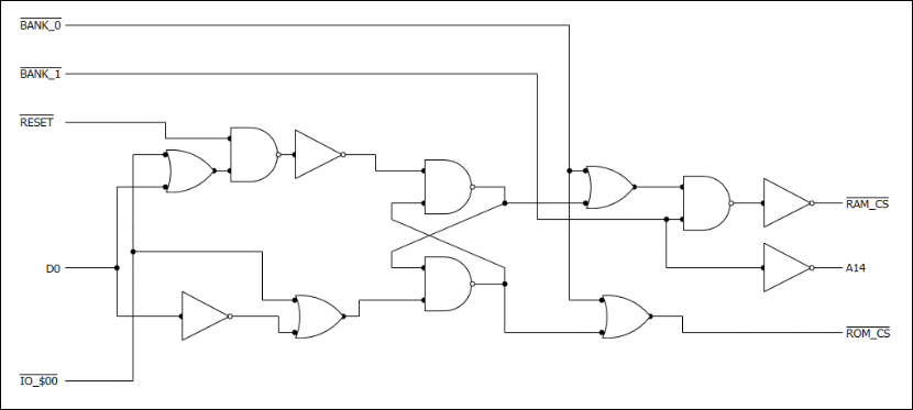
The SBC Rev 2 now incorporates a circuit to allow Bank_0 to be switched between 16K of ROM or the lower 16K of the RAM chip. The upper 16K of the RAM chip is permanently assigned to Bank_1.
Peter implemented this to work towards porting CP/M to the M62 system eventually. He is using the bank switching function in the M62 Operating System he is currently developing. |
 |
| ZB64EC-bus Info | Bus Layout |
|
Designed by Don Prefontaine and Peter Murray, based on Peter's M62-bus.
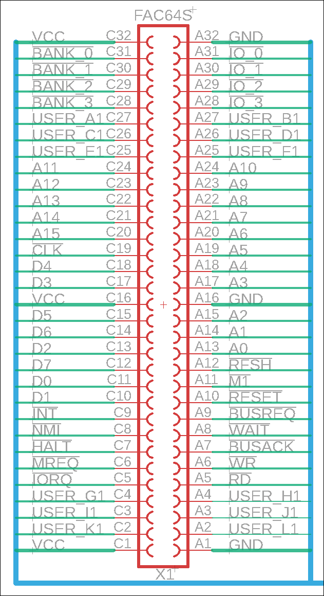
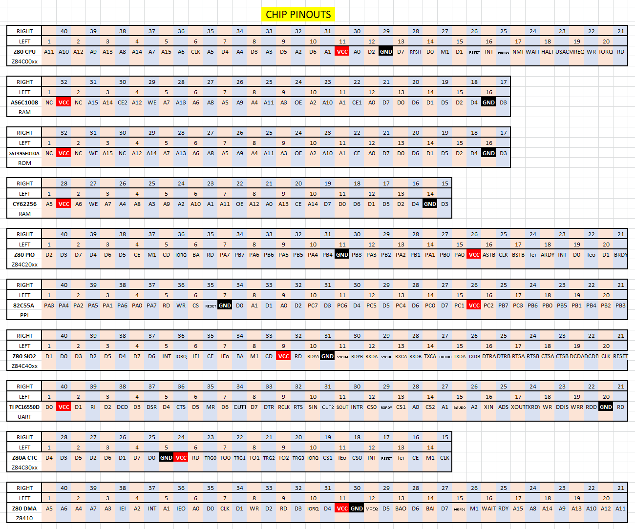
The ZB64EC bus uses the Eurocard style of connector which utilizes 3 rows of 32 pins. Layouts of 32, 64 or 96 connection pins are possible. The Z80 CPU bus only requires 40 pins so we'll use the 64-pin configuration.
The bus design is based on the straightest path from the Z80 CPU to the backplane. It does this by following the Z80 family chip pinouts as shown in the adjacent diagram (click to enlarge).
Connections between different cards/boards connected to the backplane are possible via User bus lines. There are a total of 12 lateral User lines (User_Ax to User_Lx) available.
User lines are USER_A1 to USER_A6, USER_B1 to USER_B6, up to and including USER_L1 to USER_L6.
An implementation example would be to connect the CPU/ROM/RAM board to the Bank 0 ROM/RAM Switch circuit (described above in the M62 bus) mounted on a different board. As you can see from the logic diagram, we would need to be able to connect the RAM_CS and ROM_CS lines on the CPU card to the Switch card. Bus line User_A could be connected from slot 1 to slot 2 (via a jumper from User_A1 to User_A2) for ROM_CS. Bus line User_C could be connected from slot 1 to slot 2 (via a jumper from User_C1 to User_C2) for RAM_CS. Bus line User_E1 (RESET, active high) could be connected from the CPU card in slot 1 to the UART card in slot 3. The active-high RESET signal would need to be carried from slot 1 to slot 6 because it is used by several different Zilog devices.
Each User bus line can be optionally terminated at slot 1 with a 10K pullup resistor or at slot 6 with a 4.7K pulldown resistor.
With 12 User lines each with a jumper to the adjacent slot, these 3 areas (slot 1 to slot 2, slot 3 to slot 4, slot 5 to slot 6) could potentially become 36 separate User lines. You could jumper slots 1, 2 and 6 together. It's up to you as to how you wish to connect them.
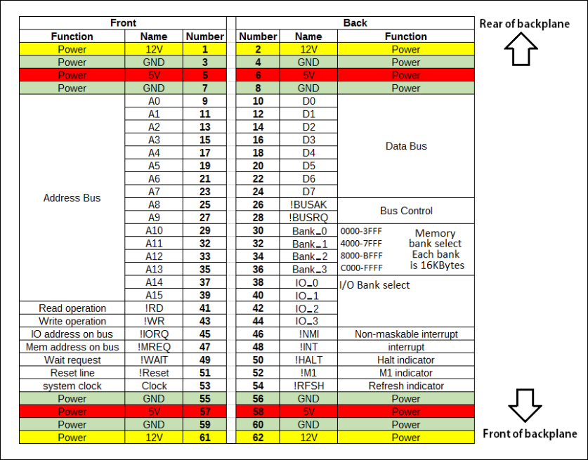
Adjacent is the portion of the schematic showing a ZB64EC-bus female backplane slot.
|
 |
![]()