|
Build Your Own Z80: PARTS |
| Parts List, Recommendations and Guidelines | Parts |
|
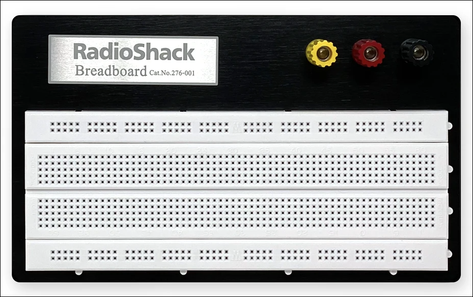
Breadboards Use quality breadboards (BBs) or suffer later with poor connections. BB Recommendations: 1) Radio Shack For the Radio Shack unit, remove it from the aluminum mounting board. You can now join them together laterally and "vertically".
For the Circuit Test unit, you can use 5v/3.3v power supplies that mount on the end of the BB. The Radio Shack unit is very high quality but is unfortunately too large for the BB end power supply. When joining two breadboards, use a snap-off utility knife to remove one of the power rails between the two breadboards, and set it aside. You may wish to use it as a power rail for a large configuration of breadboards like what you see below right.
|
Click
images to enlarge
|
|
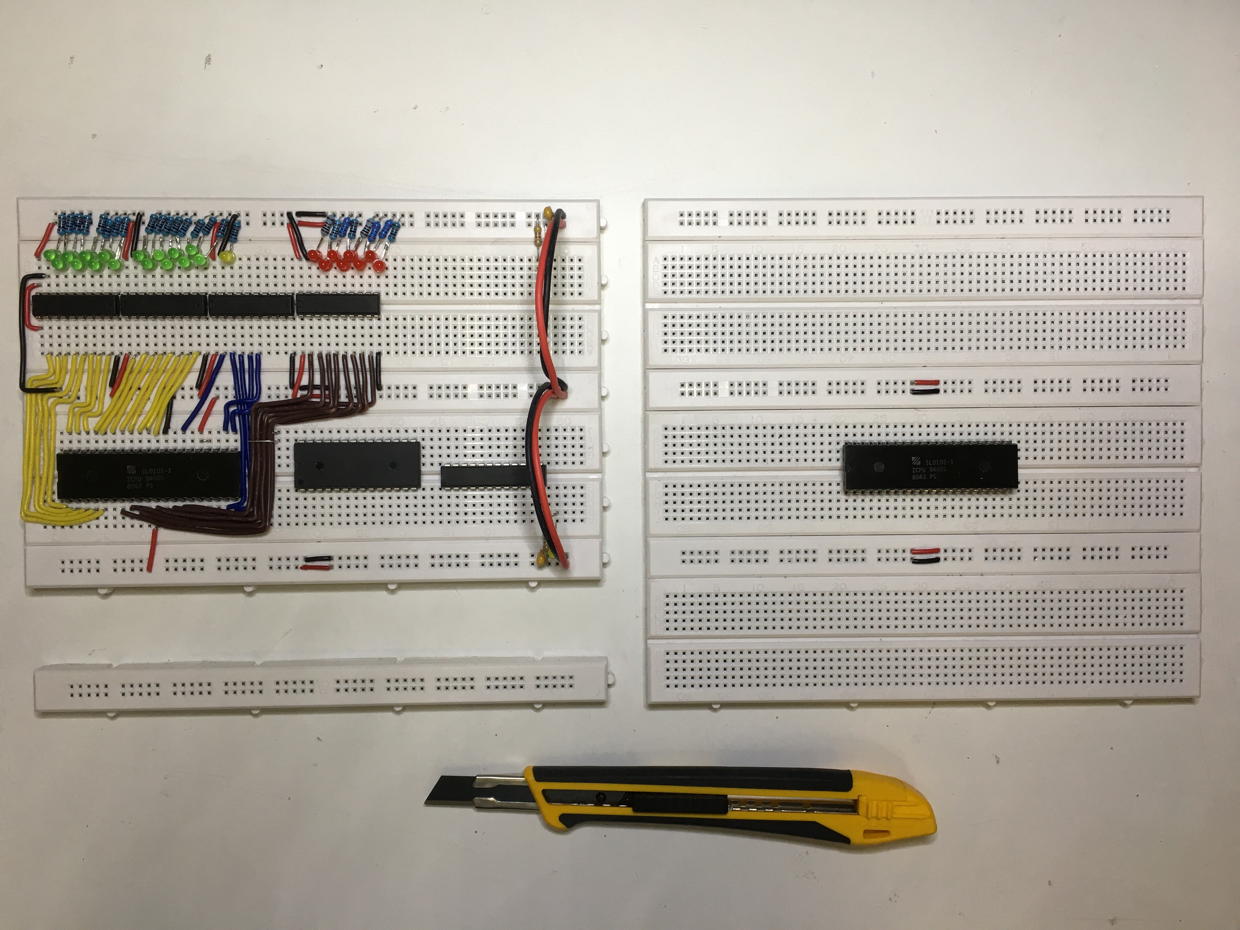
Jumper Wires There are lots out there and a lot of them are crap. For Male-to-Male (M-M) jumpers, there's one type I recommend for a solid connection in almost any breadboard; they're called machine pin jumper wires. 1) Radio Shack 2) Digikey.ca Note: If you attempt to use "flying" jumper wires (not laying on the breadboard like in the left-most picture above), it will be hard to see LEDs, connections, etc. if you're filming from overhead. |
 |
|
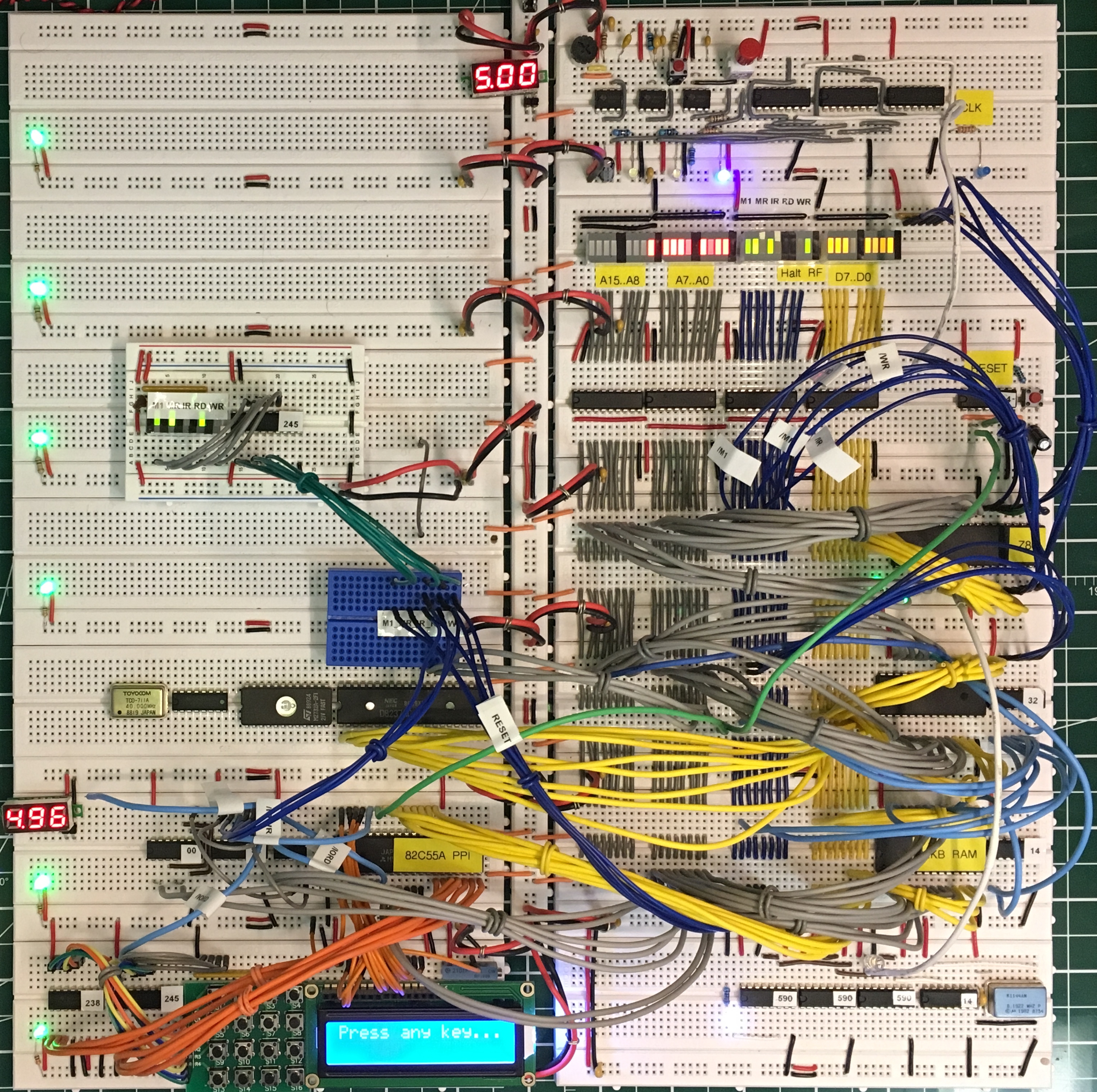
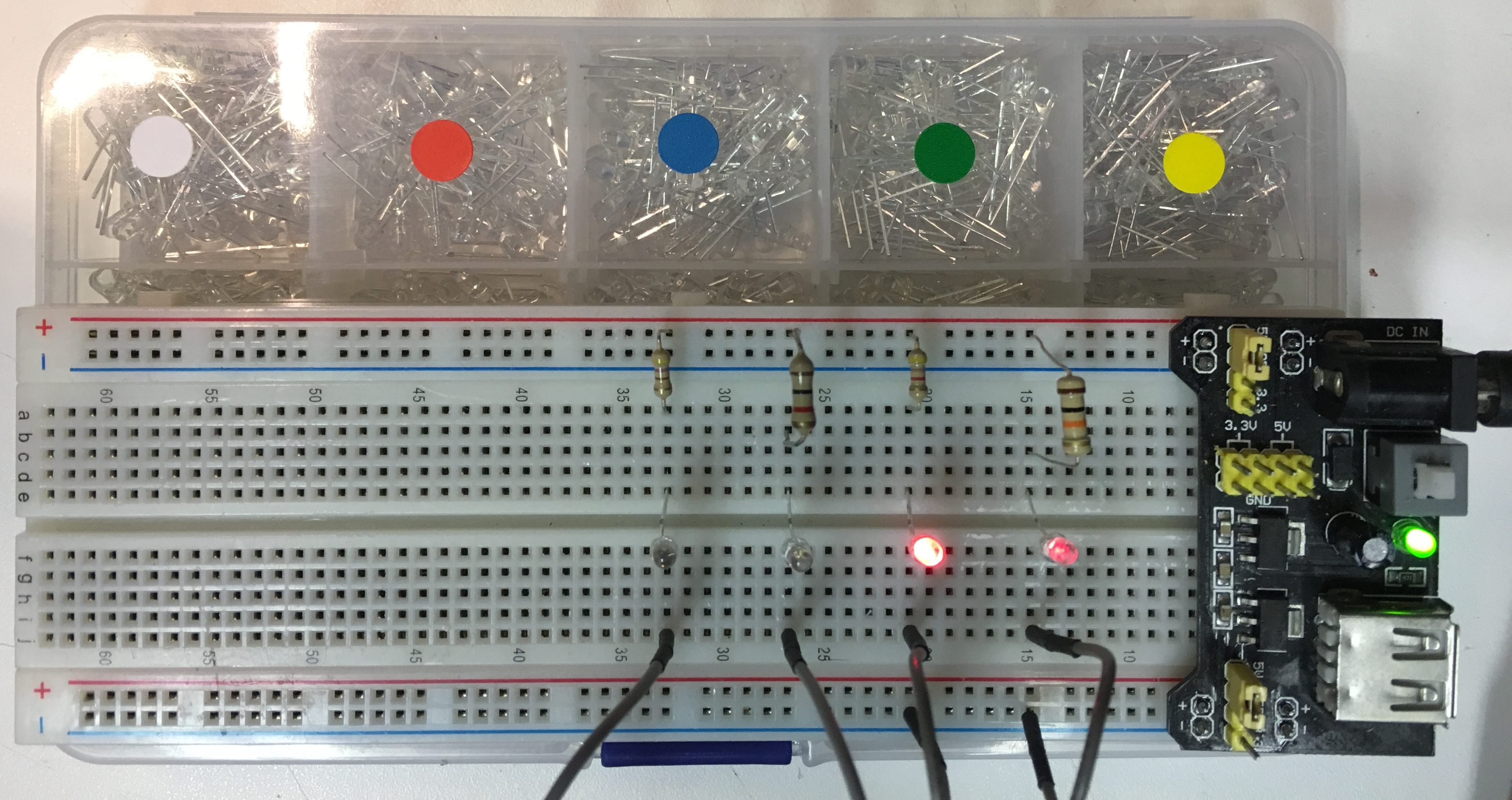
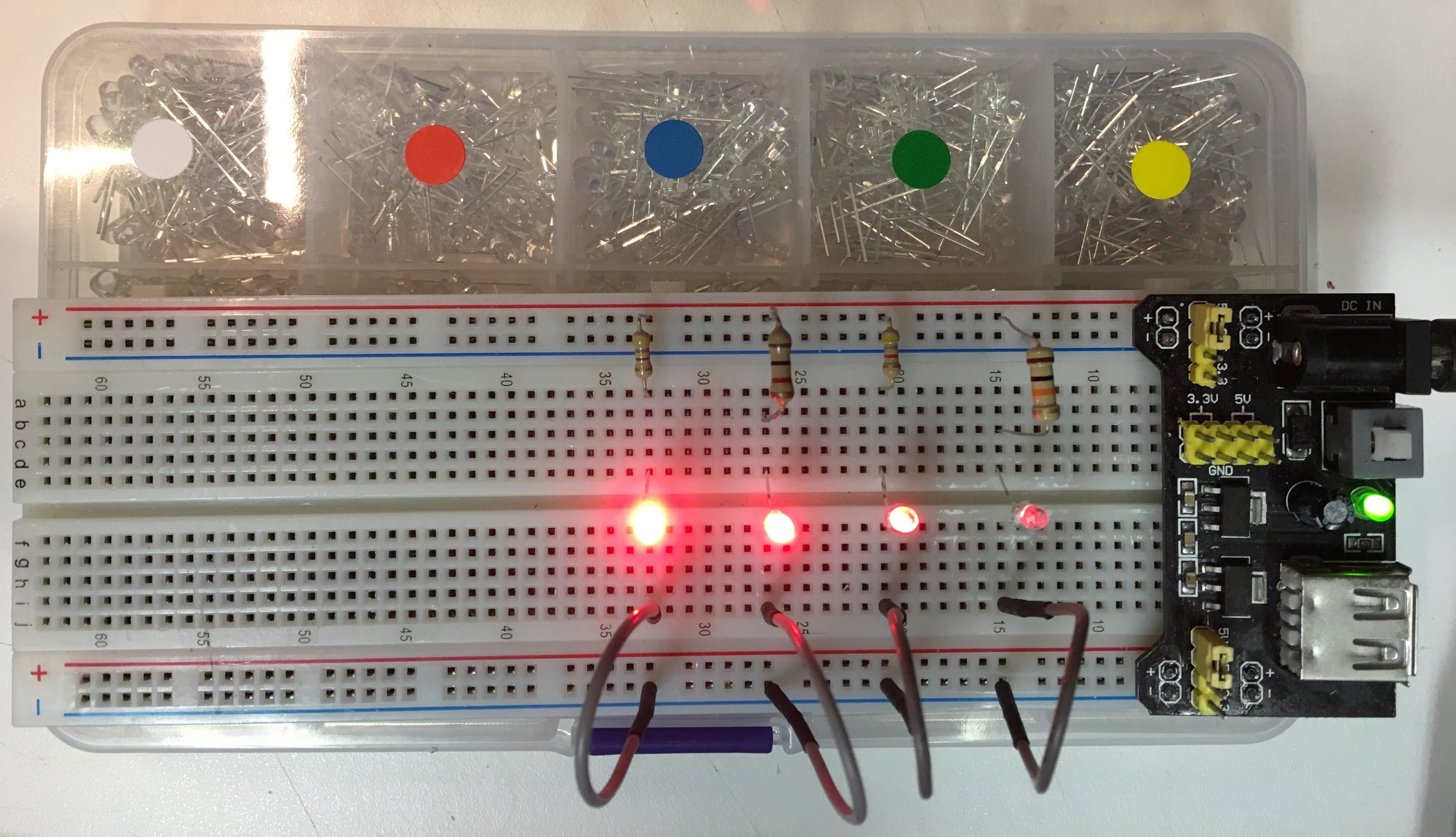
Reducing Glare If you plan on photographing or filming your Z80 board, reduce the LEDs' brightness (with larger value resistors) now rather than later when it's hard to get at anything. Here's a new LED I've started to use lately. If you examine the right-most picture in this column two panels above, you'll see a green LED on each of the left breadboards. Notice how you can easily see that they indicate the individual breadboards are powered but their brightness does not overwhelm the camera. They are current limited with 10k ohm resistors - that's right - 10k ohm! Adjacent to this panel are 3 pictures. The left-most pic contains conventional 3mm LEDs: you need to tweak your resistor values (130 to 2.5k ohms) for each color/colour to minimize the brightness for your pix. Now check out the two pix to the right of these pix. The middle pic shows 4 LEDs of which only 2 are lit. The right pic shows all 4 LEDs lit. The values from left to right are 470, 1K, 4.7K, and 10K ohm. The camera is not mounted directly over the 10k ohm LED or you would see a nice, pleasant glow without the bright saturation of the left-most lit LED that's current-limited by a 470 ohm resistor. The middle pic shows just the 4.7k and 10k current limited LEDs. Under the MB-102 breadboard is the container in which the LEDs are packaged. The LEDs are clear when not powered, hence the reason each container "pocket" has a sticker to indicate its color/colour. I really like these low current LEDs; I hope you will, too. |

 |
|
Current Limits The Z80 has a 120mA overall current budget, and a per pin limit of about 1.5mA. Don't attach current-limited LEDs to any of the CPU pins unless you want to 'cook' your CPU; isolate the signal lines from the LEDs by using driver chips like the 74HCT245. |
|
|
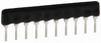
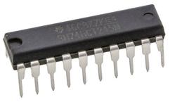
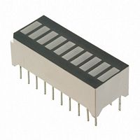
Driving LEDs or Terminating Signal Lines - 74HCTxxx may be the best low-power, high-speed, TTL-compatible ICs to use with your Z80 system - Consider the 74HCT245 drivers to light up your LEDs or LED Light Bars - 330 ohm resistor packs can be used to terminate the LED Light Bars without dominating your breadboard - 4.7K ohm or 10K ohm resistor packs should suffice for signal termination: 4.7K for pulldowns and 10K for pullups; your experience will tell you which works best. |
|
|
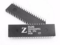
CMOS Z80 CPU versus older NMOS Z80 CPU? - CMOS appears to be the less quirky of the two technologies for a Z80 CPU - CMOS is identified by the "C" in the product number, e.g., Z84C00xx - CMOS supports clocking from DC to the rated speed (e.g. 6MHz +) - More info can be found in the Product Brief and Specification docs as well as the Peripherals (CTC, DMA, PIO, etc.) docs
|
 |
|
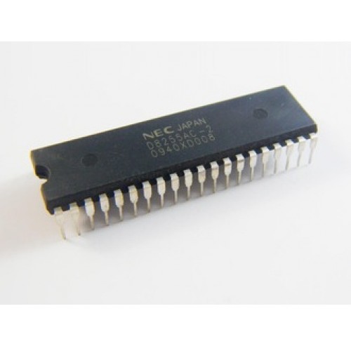
4x4 Keypad - This keypad is great for testing the I/O functionality of your 8255 PPI parallel peripheral interface chip - They are inexpensive but are not key debounced
|
  |
|
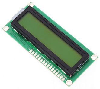
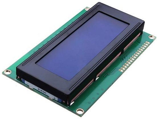
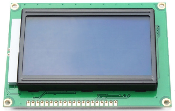
LCD Display Modules - Character, not Graphic - If you're hooking this up to an 8255 PPI/PIO device connected to your Z80, you'll need the parallel (not I2C nor SPI) interface version - 2x16 are cheap, as are 4x20 but require a change to your assemby code - The 8x16 uses the ST7920 controller instead of the HD44780U used by the other two displays, so it will require some code changes, too
|
   |