|
Z80 Programming III-c |
|
TASM .asm, .lst, .bin Files |
| Page a Page b Page c |
|
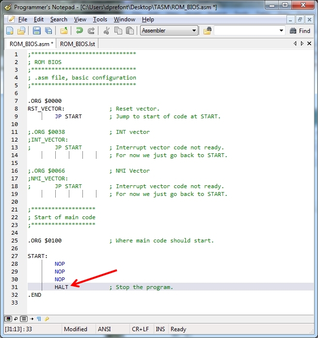
What happens next? The CPU reads the last NOP on the Data Bus as "00" which says "Do Nothing" and it does. The Program Counter (PC) advances to address $0103 where it expects the next instruction and there's nothing there. Well, that's not entirely true. If we programmed the code above into our EEPROM burner, it would run whatever code follows, even if it's $FF. So, how do we fix this situation? Add a "HALT" instruction after the last NOP and before the ".END" directive. The CPU's PC will stop advancing beyond address $0103 and just spin. Well, it actually just runs NOPs. Seriously, that is the normal operation when a "HALT" instruction is encountered - it runs NOPs until an Interrupt is encountered. See page 14 of the Z80 CPU manual.
Halt Let's add a Z80 assembly "HALT" instruction after the last NOP and before the ".END" assembler directive, assemble the file, and then decode it with XVI32. You can see the results below.
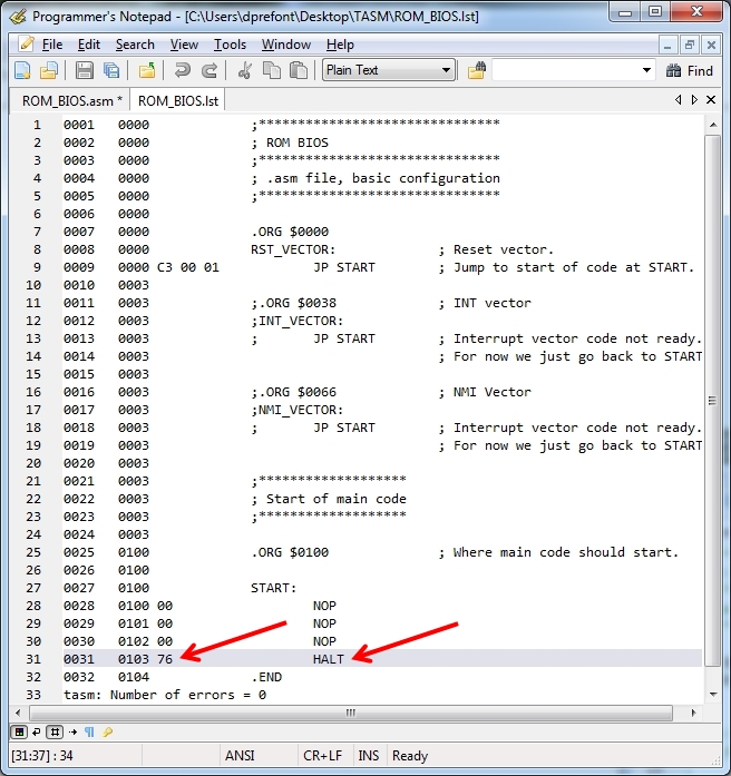
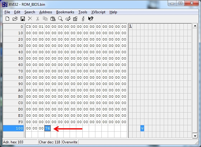
From the .LST file above, we can see the one-byte instruction HALT is the machine code "$76". When we examine the .BIN file below, we can see the "76" at position 103 after the NOPs.
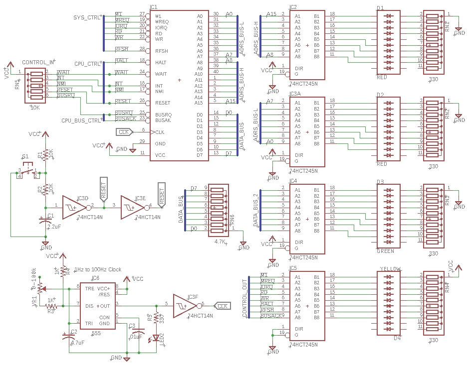
Video: NOPs Causing Z80 Program Counter to Advance Clicking on the adjacent thumbnail .gif above will provide an HD video (2.7MB, .mp4 format) showing: - Reset asserted - Low-speed clock (flashing at bottom of video) advancing the Z80 Program Counter - Address increasing in value from 0 upwards - Note that rather than just tie the Data Bus, D0 to D7, through 4.7K resistors to ground, we have also added 74HCT245 drivers so that the buses can drive the LEDs without burning out the Z80 (its cumulative current budget is only 120mA) - In the center, you have the top 8 bits (A15-A8) of the Address Bus, then the lower 8 bits (A7-A0) of the Address Bus, followed by the Data Bus (D7-D0). You will not see the Data Bus LEDs illuminate while this program is running because of the "00" NOPs - In the upper left corner the Control Bus lines are driven via a '245 to a Bar Graph. We expect to see M1, MReq, and RD active - You can see the Address Bus count upwards from 0 to about 72 ($0048) before I stopped recording. It could have gone on "forever" but at 128 ($0080), bits A7 through A15 will start to flash as the REFRESH signal is superimposed on them to keep potential Dynamic RAMs happy
Schematic: CPU and LED Drivers, Reset Circuit, Variable Clock Circuit
Summary This concludes our examination of: - .ORG and .END assembler directives - The NOP instruction, and the HALT instruction used to terminate a program - TASM .ASM, .LST, and .BIN files - Little Endian Byte Ordering |