|
ROM Monitor Tests |
|
Testing with a Serial-over-FTDI Module |
Resources |
|
Overview: To test our ROM Monitor program, we'll use the configuration involving the 16550 UART. We won't be using the 8255 PPI which is currently configured for input from the keypad and output to an LCD panel.
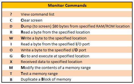
Giving Credit Where It's Due: Peter Murray of 39k.ca and I have greatly expanded Matthew Cook's Z80 monitor program from its original 3 commands to include many useful commands that can be seen in the right-adjacent panel. As of 2019/04/19, there are 11 different ROM Monitor commands. The link to Peter's web site is to his newest project - the M62 Bus System he created. It's a modular Z80-based system that supports multiple cards, including expansion RAM or ROM, which are used to break the Z80 64KB barrier; check it out.
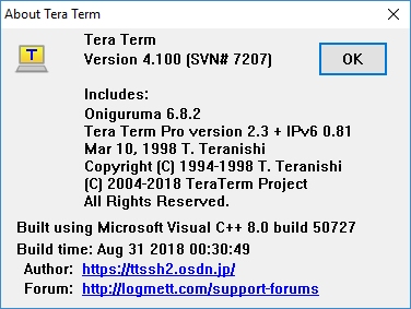
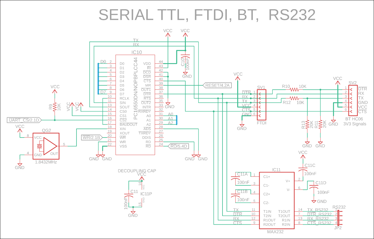
Parts: You'll need a terminal emulation program for your PC. Tera Term is simple and effective for our needs and is currently at version 4.1 Although the Serial-FTDI-RS232 schematic shows a 9-pin D-Sub connector for RS232 in the bottom left of the schematic, we're going to use the jumper block in the top center instead. You'll need an FTDI adaptor that converts USB signals from your PC to TTL-level serial signals needed by the UART: an FTDI USB to TTL Serial adaptor or FTDI Basic Breakout module. The adaptor/module may be using the FT232RL chip or the less expensive CH340G chip. With either of the FTDI driver chips, you're going to need drivers for the board for your PC's operating system. I have tested both of the chip driver links and they work fine. Warning: although some of the FTDI-USB modules can support 5vDC, they still expect to see 3.3v on their signal lines. You can run them on 5v but don't expect them to last. A workaround would be inserting a CD74HC4050 driver chip between the module's DTR, TX, RX, and CTS lines and your system, but you'll also need a 3.3v regulator for the chip's power supply. An easier workaround is to do as I have done in the PCBs section of this website: use a resistor network to step down the voltage to tolerable levels. Here's a link to the schematic; the resistor network is on the right side of the schematic. A mini USB or micro USB cable to connect your PC to the adaptor/module. Before you order either USB-to-Serial adaptor/module, keep in mind that some are 5v, some are 3.3v, and some use a jumper to select between the two voltages.
USB to Serial Installation Guide: Install the FTDI drivers, then install the adaptor/module when prompted by the PC operating system. Keep in mind there are two different FTDI chips out there as mentioned earlier, with the most common one from the off-shore boards being the CH340G chip. Plug the 6-pin FTDI adaptor into your breadboard. Provide +5v and Gnd to it. The pins are most likely labeled, left to right: DTR RxD TxD Vcc CTS Gnd You should connect these adaptor pins to the corresponding pins on your jumper block. In the schematic in the adjacent panel you may have noticed that DTR and DSR are tied together, RTS and CTS are tied together, and RI and DCD are pulled to ground. The RS232 spec states that DTR/DSR are "I'm here" signals between the DTE (terminal) and DCE (modem) on the local side. (In typical serial communication, there is a corresponding arrangement on the remote side.) Additionally, RTS/CTS are hardware flow control signals between DTE and DCE but these have often been replaced over time with in-stream flow control via XON and XOFF ASCII commands between local and remote ends. You may still see RTS/CTS flow control between DTE and DCE on the local side. And finally, RI (DCE) and DCD (DCE) relate to waking up the remote end of the "call" when establishing a link. Vendors no longer seem to adhere to the original RS232 spec that I studied and implemented extensively while working at Gandalf Data Systems between '87 and '93. Vendors repurpose many of the RS232 control signals for own needs. For example, AutoReset is a feature that allows you to upload a compiled sketch to an Arduino board without pressing the reset switch. The way it works is by sending a reset signal (GND) to the reset pin using the DTR signal on the RS-232 interface. NOTE: The 16550D UART Schematic has the oscillator pins mislabeled: GND should be 4 and VCC should be 8.
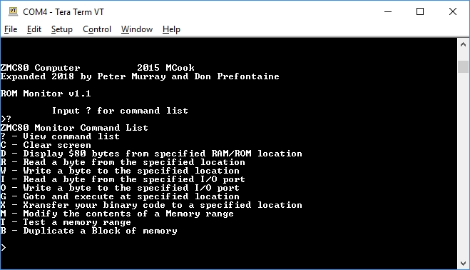
How do I test my circuit? Ensure your Z80 system is running. Connect a USB cable between the serial FTDI module and your PC. Start up the terminal emulation software on your PC. Press your Z80's Reset button. This should display the opening screen with the monitor version and coding credits. In the PC terminal software screen, press the "?" key to get a list of ROM Monitor command; it should be the same as those shown in the right-adjacent panel. In the adjacent panel there is also a link to a video that walks you through several of the ROM Monitor commands.
How do I get this program onto my EEPROM? The 9600bpsROMmonitor.zip file contains the .asm assembly code file, a .lst file showing the machine code and assembly code, and an .obj file that contains just the machine code; the .obj file is in binary format. (Most EEPROM "burners" will support either a binary file or an Intel .hex file.) You will need to configure your terminal emulation software and port for 9600bps. If you have not been following along up until now, it's time to consider buying a real EEPROM burner. Here's one that I have been using for about 12 months. It's easy to configure, easy to setup and use each time, and very reliable; it's a TL866 II Plus. Don't get the plain TL866 if you can afford the TL866 II Plus. I bought mine on eBay for $54.14us with free shipping, and it took 2 weeks to arrive from Shanghai CN. You'll also need the bag of converters if you plan to run any non-DIL chip in your project. An example would be the 16550 UART available in 44PLCC package that takes up a lot less room on your PCB. The adaptor means you can run the chip in your breadboard. |
Eagle CAD: Serial-FTDI-RS232 Schematic
Tera Term VT Terminal Emulation Program
ROM Monitor Commands
Short Video: ROM Monitor Tests
Clicking the thumbnail gif above will provide an HD video (4.5MB, .mp4 format)
|
|
Testing with a Serial-over-Bluetooth Module |
Resources |
|
If you would prefer to connect to your Z80 system with serial-over-Bluetooth instead of serial-over-FTDI and a USB cable, add an extra female 1x6 connector to the circuit as shown in the schematic in the adjacent panel. You plug your serial Bluetooth module into your Z80 system instead of the serial FTDI module and you will be able to communicate with your Z80, providing you stay within about 10m. Communication appears to be limited by the vendor to 9600bps, 8 bits, No Parity, and 1 Stop Bit which is plenty fast for interactive work with the ROM Monitor. The vendor indicates you must adhere to the protocol of 8N1 but there is no mention of a speed limitation; you might want to try faster speeds. Don't forget to set the speed in the line 28 of UARTDriver_DON.asm, recompile with Assemble_DON.BAT, and then burn the resultant binary file Z80Monitor_DON.obj to EEPROM.
Here's a link to a cheap HC-06 serial BT module I tested that works well.
Installing Bluetooth: First things first,
remove the serial FTDI module so it does not cause grief with either
the BT installation nor operation. When the HC-06 is not
paired, a red LED continually flashes. Once paired, it flashes twice
every couple of seconds.
Do you want to mess around with your new HC-06 serial-BT module? Here's a link to check out. |
Eagle CAD: Serial-Bluetooth-FTDI-RS232 Schematic 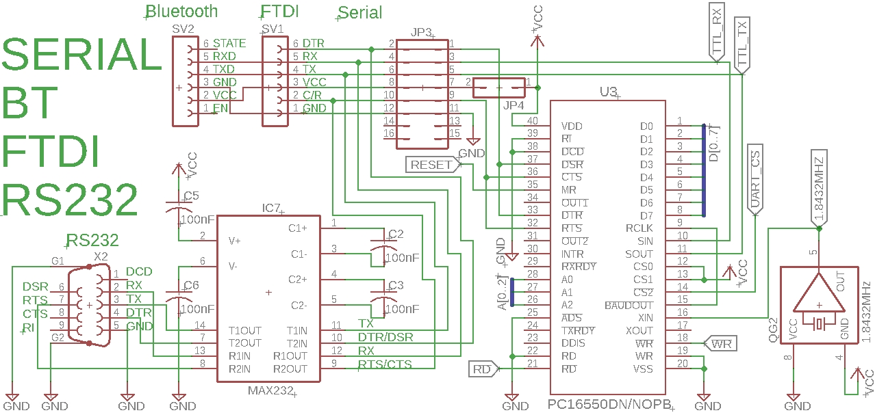
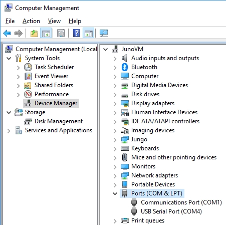
Device Manager| Ports config before adding BT device
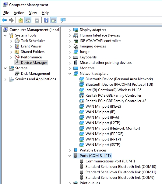
Device Manager| Ports config after adding BT device
|
