![]()
|
Part 1: Test Your Aduino SBC |
| Circuit Tests (click .gif for video) | Test: Power Supplies, USB-FTDI, I2C, OLED, RTC, micro-SD |
|
Blink Test (Click for a short video)
OLED Test (Click for a short video)
BME280 Test (Click for a short video)
RTC Test (Click for a short video)
Micro-SD Test (Click for a short video)
|
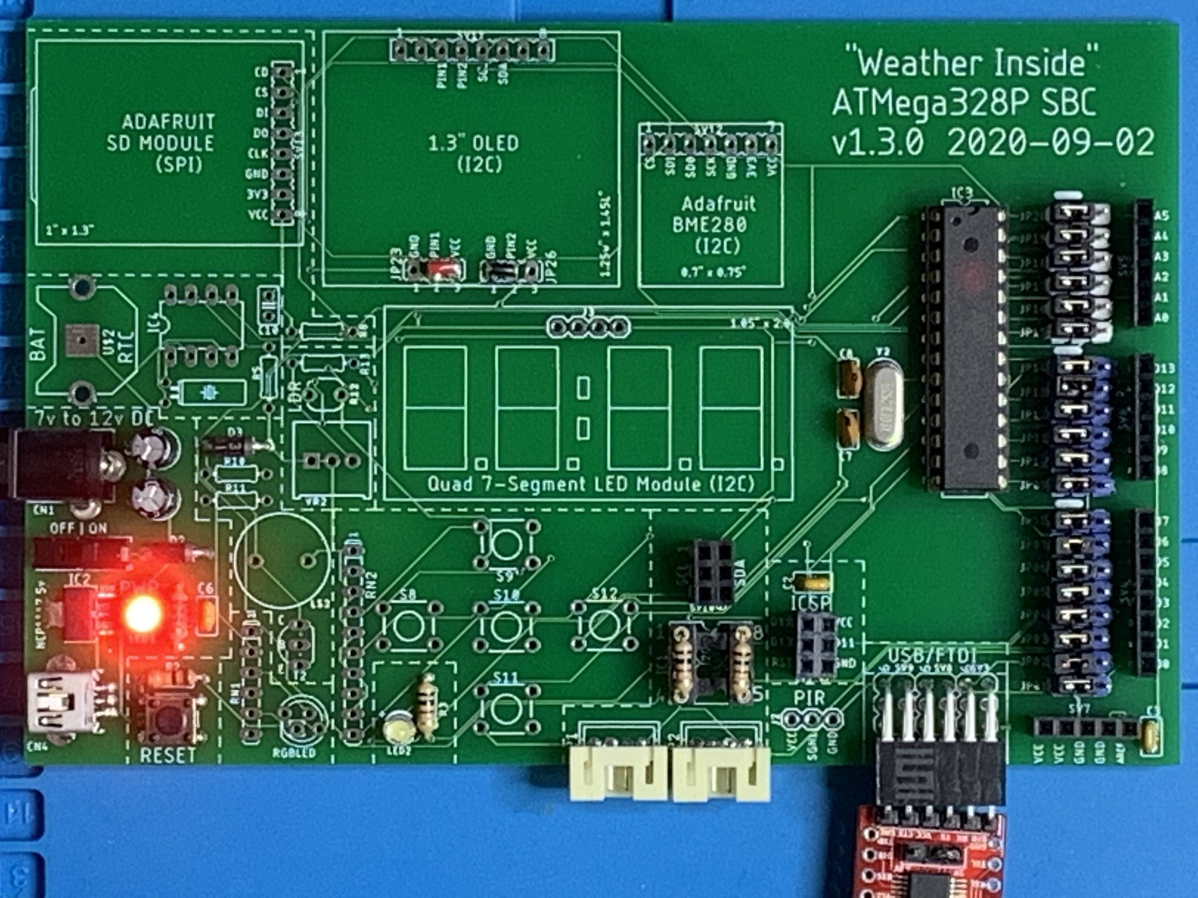
Overview We'll assemble and test the ATmega328P SBC Weather Station one circuit at a time.
Power Supplies, Reset, USB-FTDI, D13 LED Assemble the DC power jack power supply, miniUSB power supply, USB-FTDI connector, Reset circuit and the D13 LED circuit. Load "Blink_SerialMonitor.ino" and upload it to your new Aduino. You should see the USB-FTDI (lower red module in the first adjacent video) flash it's tiny Tx and Rx LEDs, and then the white D13 LED should flash according to the pattern you configured. You now know the USB-FTDI circuit is working fine as well as the LED.
Ensure C2 near the USB-FTDI connector is soldered or the programming upload will never complete with a Reset. Also, you will need jumpers for D0, D1, and D13 to complete the circuits; use the left/center jumper because center/right disconnects the circuit from the microcontroller. This real estate "heavy" design is for testing individual circuits. If someone made a SPDT (3 contacts) dipswitch with 6 or 8 positions, this would be a more efficient design.
I2C, Pullup Resistors, 1.3" OLED An 8-pin socket is used to house two 1K resistors as pullups for SCL and SDA. If your calcs or "gut" tell you to increase to 2.2K or 10K if a device you want to add to I2C is already terminated high, you can easily do so without breaking out the solder sucker.
To physically support the 1.3" OLED display, make the solder connections for PIN1 and PIN2 as either VCC/GND or GND/VCC using small insulated jumper wires. It's hard to see in the photo on the right, but that's what I've done with the little red wire and black wire jumpers. Also, you will need jumpers for A4 and A5 to complete the circuit; use the left/center jumper because the center/right jumper disconnects the circuit from the microcontroller. OLED Support (click to enlarge)
I loaded the "ssd1306_128x64_i2c.ino" trace found in the Arduino IDE under "File|Examples|Adafruit SSD1306" and made a few changes: - line 30: change "#define OLED_RESET 4" to "#define OLED_RESET -1" - line 59: change "if(!display.begin(SSD1306_SWITCHCAPVCC, 0x3D)) {" to "if(!display.begin(SSD1306_SWITCHCAPVCC, 0x3C)) {" These two lines will advise the driver there is no separate digital line to handle Reset, and change the I2C address to 0x3C. I saved the file to OLED_4-Wire.ino, uploaded it and watched the Adafruit graphics demo. This is what you are seeing in the adjacent video.
BME280 Sensor The next test uses portions of the "Weather_Inside_SD_Tone_Flash_2h.ino" file to test both the BME280 Temperature/Humidity/Barometric Pressure sensor as well as the OLED we tested earlier. Content will also go to the Serial Monitor running at 9600bps (default). The needed test file is "BME280_OLED_Test.ino". Upload it to your Aduino. Expect the display to blank briefly every 2.5 seconds. Breathe directly on the BME280 board and you should see both the Serial Monitor and OLED display reflect the change in temperature and humidity as it does in the short video. Communication to the Arduino ATmega328P is via I2C so that should be working fine.
RTC Real Time Clock You need to make a solder puddle in the center of the battery holder so it has good contact on the bottom of the battery. Once you've soldered the 5 devices that comprise the RTC circuit, leave the battery out and upload this test file, BME280_OLED_RTC_Test.ino. The date and time will be pulled from your PC. Shutdown the board, install the CR1220 battery and run the program again after repowering the board. You should now have the correct date and time. Ensure the USB-FTDI is not connected during this testing time, and use the power switch to turn off the power for at least 5 seconds. When you turn it back on, the correct date and time should be present in the OLED display. Communication to the Arduino ATmega328P is via I2C, too.
Micro-SD Board Once resistor R8 and the Micro-SD Card module are soldered onto the SBC, you will need to ensure the following are also jumpered: - D3 for card detect - D10 through D13 for SPI communication
The Arduino test file, BME280_OLED_RTC_SD_Test.ino, continues with the previous test modules you've worked through and has added a test for the micro-SD card module, too. You may notice in the file that all of the text printable by the Serial Monitor is prefaced by "F()". This is to move the text out of global variables and into regular memory. Failure to do so will result in a "Low memory resources can lead to unstable operation" or something like that, the result being is that sometimes the display and sensor will work and sometimes they won't. In the test file, the display is blanked briefly every 5 seconds and the data is written to the SD card every 5 seconds, too. You can see the tiny red LED flash in the upper left corner of the adjacent video. You would probably want to use 10s/60s once everything tests out fine. |
![]()
Tags: Arduino-type Microcontroller, ATMega328P
![]()