![]()
|
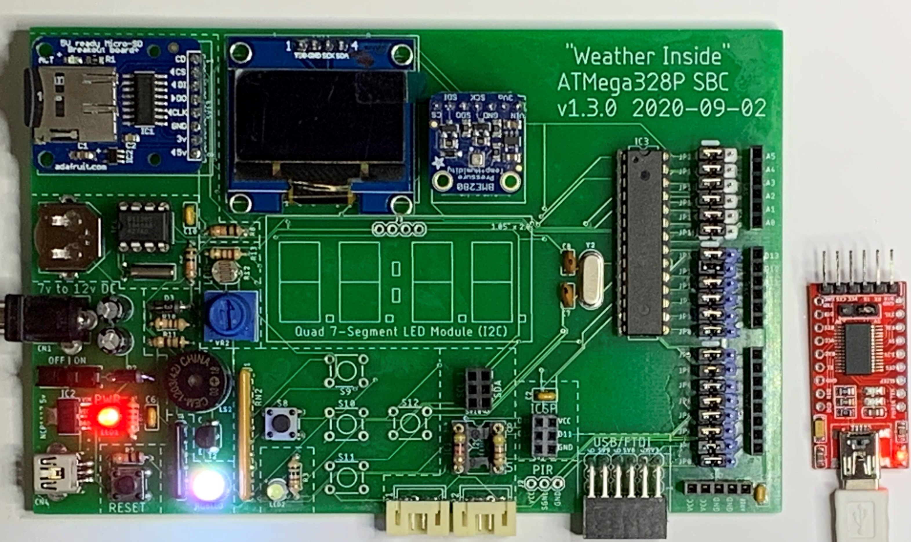
Part 2: Test Your Aduino SBC |
| Circuit Tests (click .gif for video) | Test: RGB, Buzzer, LDR, Switch Matrix, PIR, Quad 7-Segment LED Backpack |
|
RGB Test (Click for a short video)
Buzzer Test (Click for a short video)
LDR Test
Test 5 Switches (Click for a short video)
PIR Motion Sensor Test (Click for a short video)
Quad 7-Segment LED Module (Click for a short video)
|
Common Anode RGB (red, green, blue) LED We can reuse the sketch, RGB_02.ino, we wrote for the stackable Aduino to test the RGB LED.
We have quite a few components installed on the SBC now so we can try the complete sketch used to test the stackable ATmega328P boards. There are two versions of the file available now. One is for the SH1106-based 1.3" OLED and the other is for the SSD1306-based one. It's easy to tell them apart once you load up the code: the SH1106 will only display a vertical line of pixels on the OLED if you try to load it up with the SSD1306 driver. The sketches are named: - Weather_Inside_SD_Tone_Flash_2h_SSD1306.ino - Weather_Inside_SD_Tone_Flash_2h_SH1106.ino Press the Reset button for a "clean" start after the file has uploaded.
Buzzer Circuit Ensure D4 and D5 are jumpered to complete the buzzer circuit. You will need to solder the 5 components that make up the buzzer circuit and you will also need to solder switch SW8 and RN2. In the adjacent video, we press SW8 connected to Arduino pin D5 to cause white LED2 to flash and for a tone/melody to play. You can test the circuit using the same test, Buzzer_01.ino, we used with the stackable Aduino. You can also upload the complete system sketch used in the test above. Don't forget to press Reset.
LDR (Light Dependent Resistor) A0 needs to be jumpered in to read the analog signal and convert it to a digital value. Upload any of the 3 LDR sketches used for the stackable ATmega328P board. With Serial Monitor running, turn the potentiometer VR2 fully clockwise while light is shining on the LDR. Your highest reading should be in the 900s. Cover the LDR and note the lowest value reached. You now have your range for coding light levels.
5 Switch Matrix We'll use the RGB to test the 5 switches: Left, Top, Center, Bottom and Right. Each key press will yield a colour combination unique to that key" - Left: red - Top: Purple - Center: Green - Bottom: White - Right: Blue You will need the following jumpered on: A1, A2, A3, D5, D6, D7, D8, D9. Upload the test file, Switches5_LEDs.ino to test the switches and the RGB LED again.
PIR Motion Sensor D2 needs to be jumpered in to read the digital signal as on or off. Upload the "Weather Inside" sketch used earlier in testing the RGB LED. Note that the timing is normally 10s to display the OLED before blanking, and 60s before writing the stats to the microSD card. We have reduced both to 5s as you can see in the adjacent video.
Quad 7-Segment LED Backback I2C Module You will need the Adafruit library for this I2C device. Upload the HT16K33.ino sketch to test your display. For your final test of all systems, upload either of these two depending upon which OLED you have installed:
At this point, all of the circuits should be working fine. If any one is not, consider disabling the Arduino resource by moving the male jumper from left to right. You can then build the circuit on a breadboard and use jumper wire to connect to the female resource pin to see if it works properly when not actually on the PCB. |
![]()
Tags: Arduino-type Microcontroller, ATMega328P
![]()