![]()
CIRCUITS & TEST SKETCHES
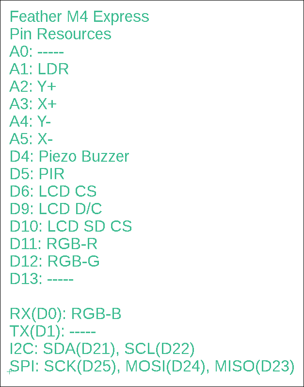
The largest, feature rich Weather Inside system you can build is M4_4Box_24LCD_MBC.
It's an Adafruit Feather M4 Express paired with a 2.4" LCD/TFT/SD in a larger Hammond 1591XXS project box.
Modify any of the sketches listed below to accommodate this system's Resource Pin List.
(Remember to click any image for a larger one.)
| Video |
Device and I/O Pins |
Sketch(s) |
Description/Comments |
 |
RGB LED - D11, D12, D13
|
|
Red, green, blue LED with common anode (+) connection. The first program sequentially lights/extinguishes each LED colour. The second program uses the analog pins to mix colours. The RGB LED and resource pin numbers are the same as used in the "final" sketch, M4_FeatherExpress_4Box_MBC__03.ino In this sketch, the Blue LED is on as long as the LCD display is lit. The Red and Green LEDs illuminate briefly every 60s when the stats are written to the microSD drive. Additional info: Calculate resistors for RGB LEDs. |
 |
Piezo-Buzzer Speaker - D4 |
When a switch is pressed in the adjacent sketch, an LED is illuminated and a brief tone/melody is played on the piezo buzzer. The time between the (up to 10) tones can be varied. In the adjacent video, movement is detected which causes the LCD to display and the blue LED to illuminate. After about 8s, the display ceases as does the blue LED. A 12s timer (normally 60s) expires and the stats are written to a microSD card. At the start of the write the green LED flashes, and at the end of the write the red LED flashes. The buzzer can be heard briefly during the write. This can be found in the sketch M4_FeatherExpress_4Box_MBC__03.ino |
|
 |
PIR Motion Sensor Module - PIR: D5 - RGB LEDs: D11, D12, D13 |
The red LED connected to D11 will illuminate when the signal from the PIR (connected to D5) goes from 0v to 3v3 after detecting movement. Note how the LED stays lit until the movement ceases. This can be found in the monPIR() portion of the sketch in M4_FeatherExpress_4Box_MBC__03.ino |
|
 |
microSD Card Module - SPI: SCK, MOSI, MISO - D10 (CS) |
Link to more SD functions |
Write a test file to the SD card. List the SD card's files in the root folder. List the SD card's folders and files. |
 |
LDR: Light Dependent Resistor - LDR: D3 - LEDs: A1, A2, A3 |
LDR_3LEDs.zip | Three LEDs arranged like a traffic light, illuminate in succession as the light above the LDR is reduced. |
 |
DS1307 RTC or PCF8523 RTC Real Time Clock - I2C: A4 (SDA), A5 (SCL) |
DateTime_DS1307.zip |
Prints the current date, day-of-the-week and time on the serial monitor. Once initialized by your PC's clock, the date and time will be backed up by the coin cell battery. This link will provide info on the RTClib. This program works the same as SdFilesList but now the most recent files are timestamped with the current date & time, thanks to the RTC. In the adjacent video you can see an RTC module in the lower left corner, and the date and time on the LCD in the upper right corner. |
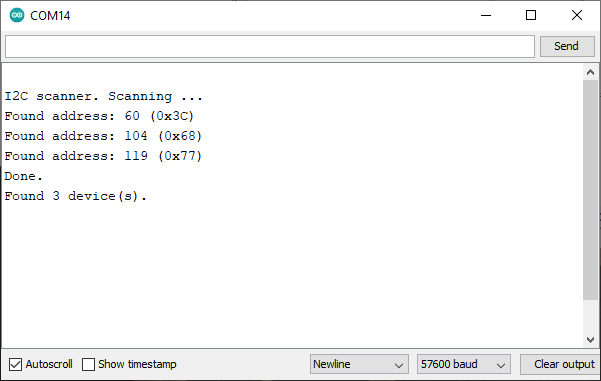 |
I2C Addresses 0x3C: OLED 0x68: SD 0x77: BME280 |
Q: How do I know which I2C addresses are in effect? (This becomes important when you cannot get a new device to work with your current system configuration.) A: Run I2C-Scanner.zip. It will give you a list of all I2C addresses currently in use. If you don't know which address is which, remove all of the I2C SCL/SDA connections, then add them one by one as you run the program. Use it to document your code for the addresses in use. Complete Adafruit I2C address list. |
![]()
![]()