Pix/Video
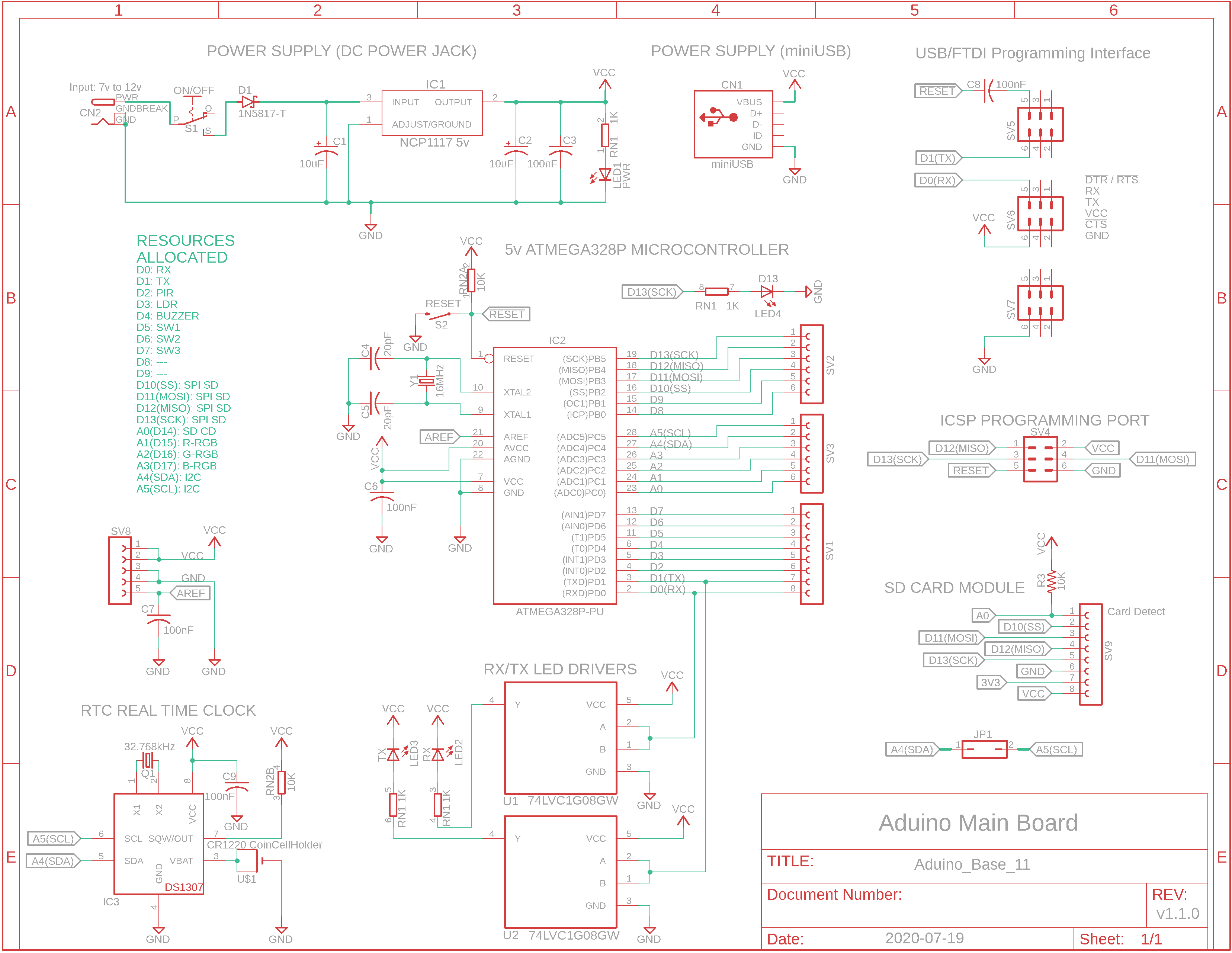
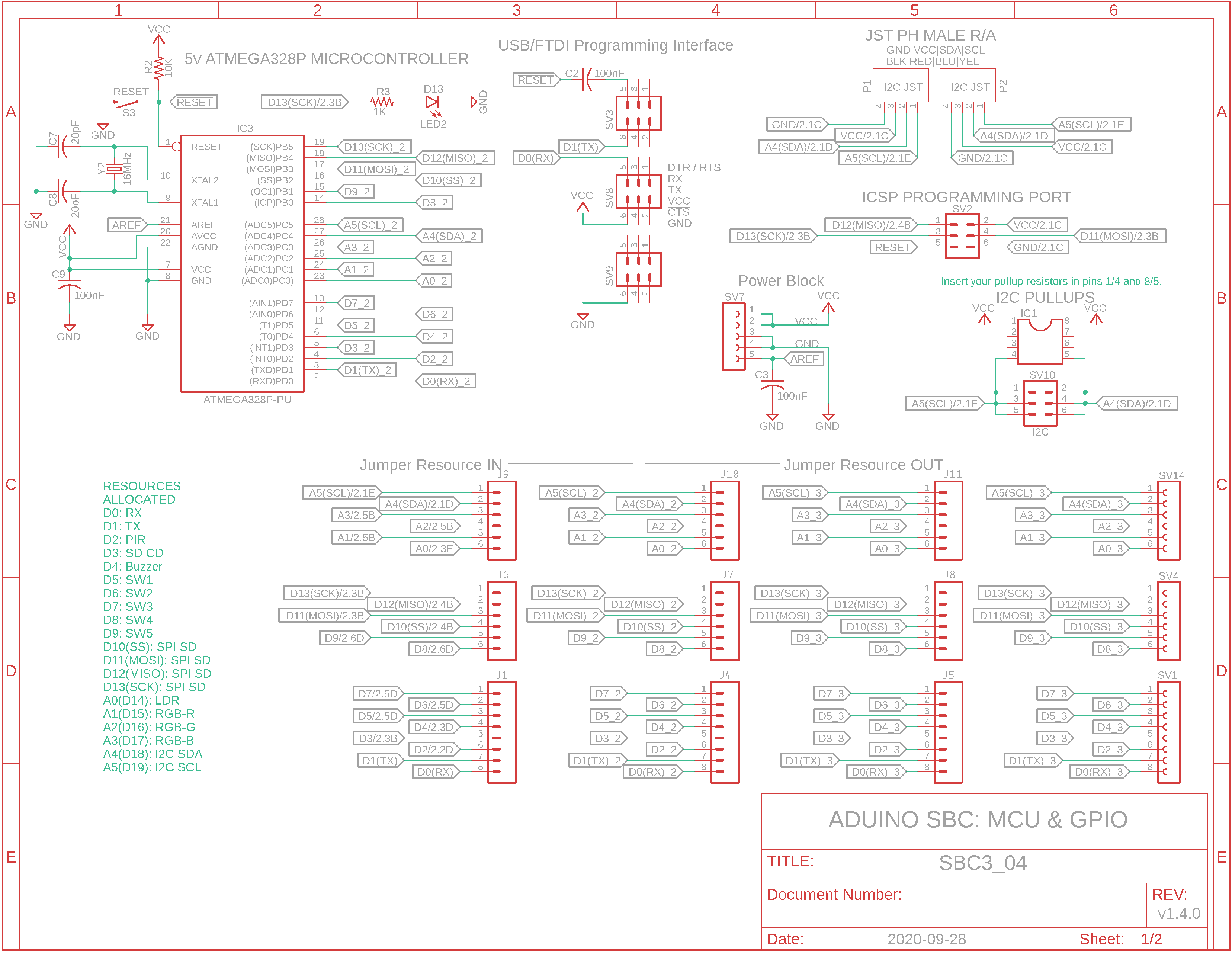
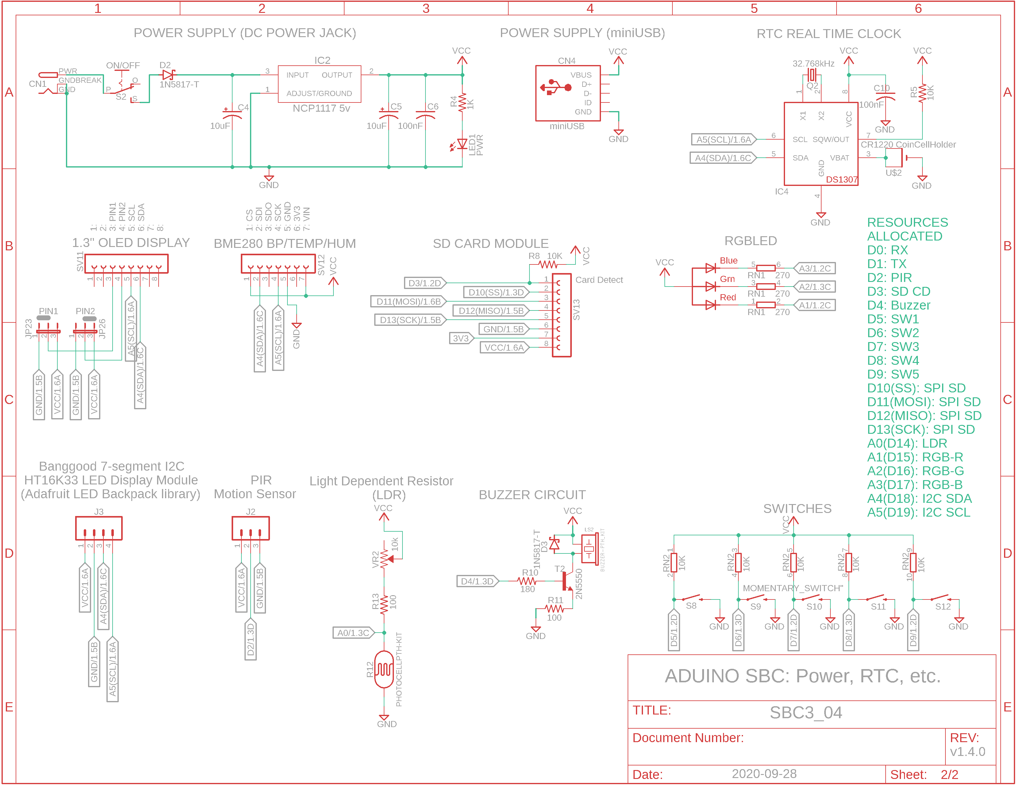
Schematics
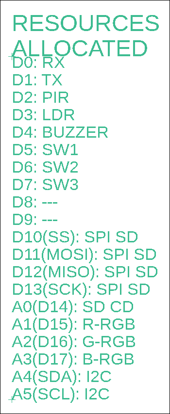
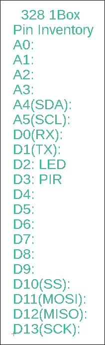
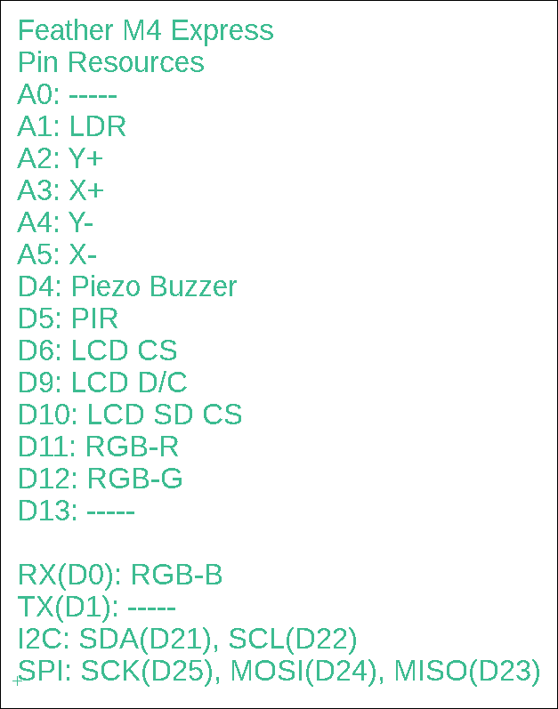
Resource Pins
Features
Stacked
MBC
(multiboard
computer)
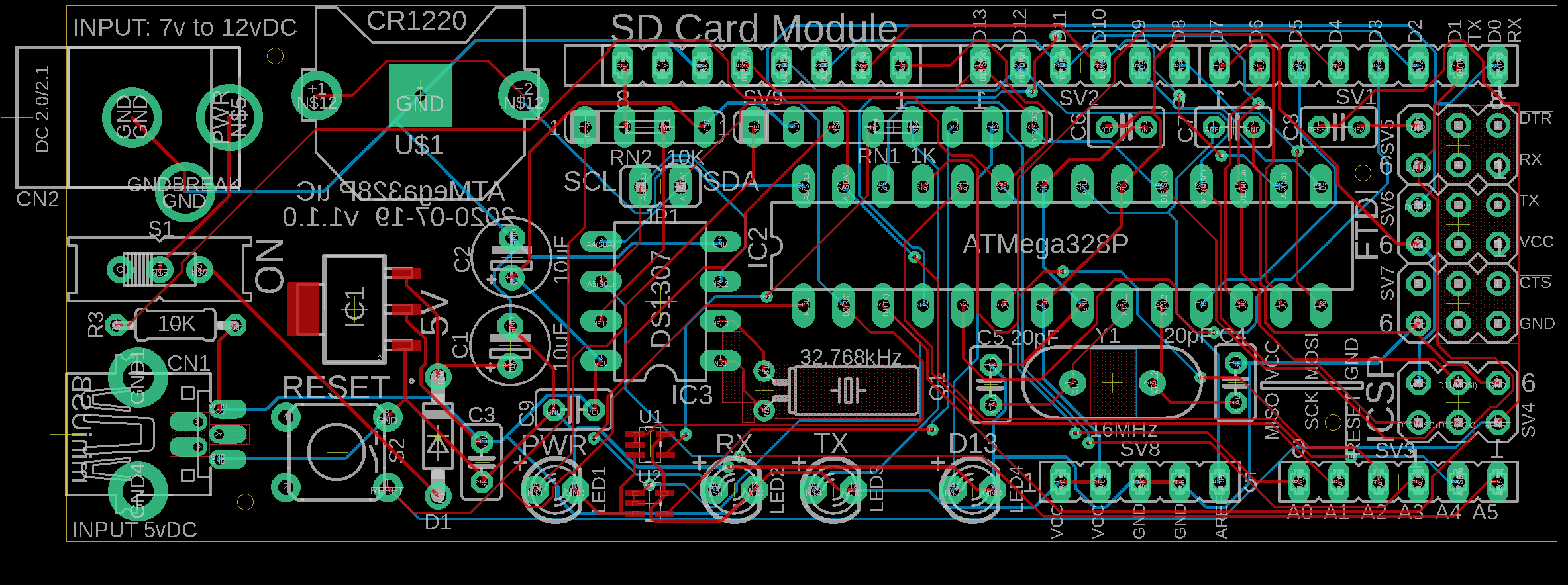
Base Board:
Base Board Bill of Materials (BOM)
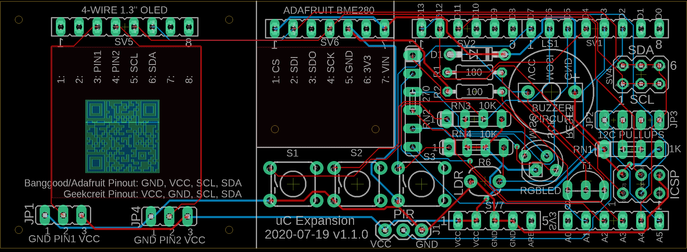
Expansion Board:

Expansion Board BOM
Stacked configuration: base & expansion boards
- ATmega328P uC
- 1.3" 128x64 OLED (I2C)
- PIR motion sensor
- Buzzer
- BME280 sensor module (I2C, temp/humidity/BP)
- RTC (I2C, real time clock & battery)
- Rx/Tx LEDs, D13 LED, RGB LED
- microSD module (SPI)
- USB/FTDI programming port
- miniUSB and barrel jack power connectors
- LDR (analog light dependent resistor)
- 3 momentary switches
SBC
(single board
computer)
SBC
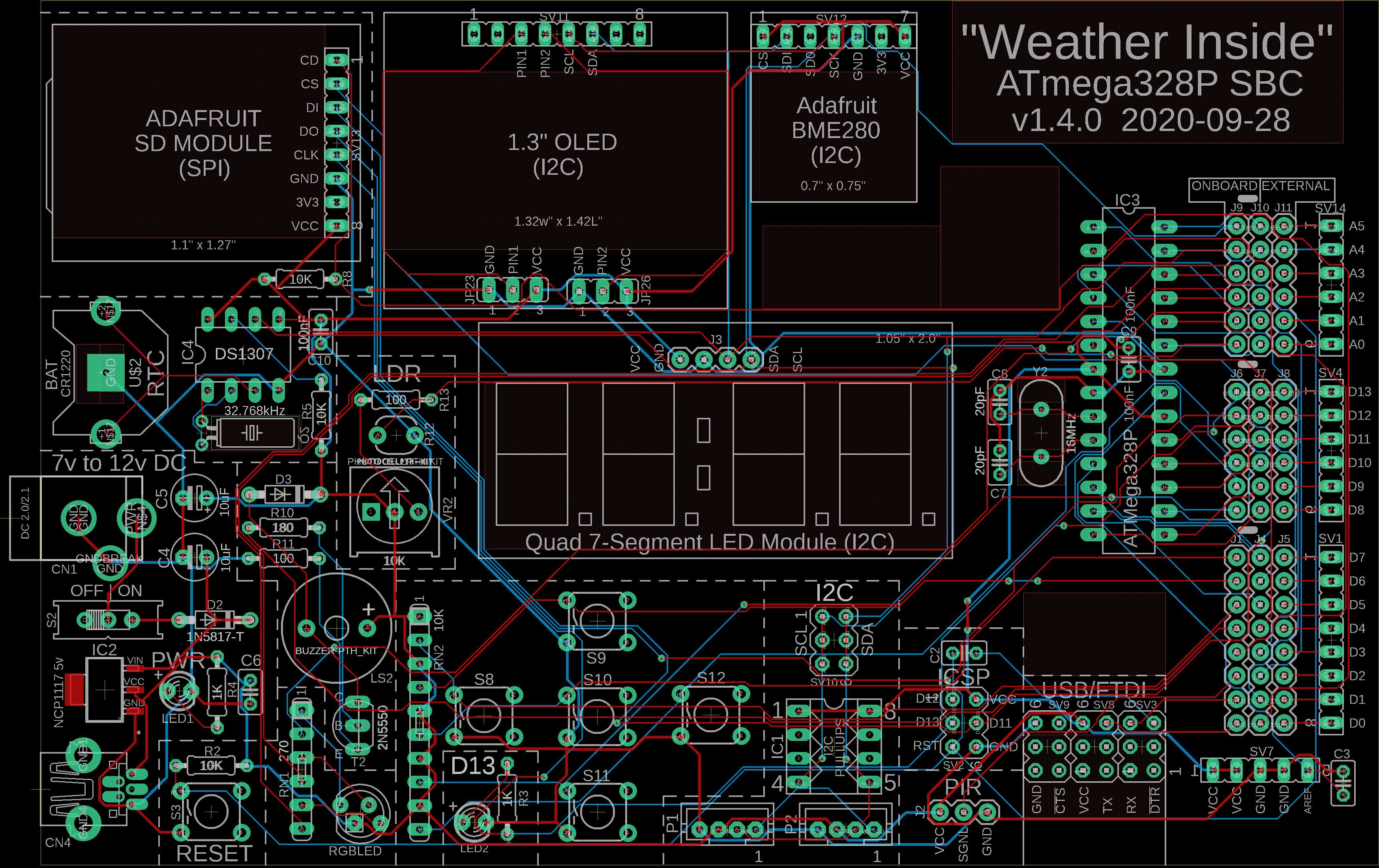
SBC BOM
Sketch: Weather_Inside_SSD1306.ino

SBC (single board configuration)
Same as stacked configuration with these changes:
- 5 momentary switches
- I2C JST receptacles
- Jumpers to disable onboard resource so the pin can be used externally
- Socket to swap I2C pullup resistors
- LDR with adjustable bias resistor
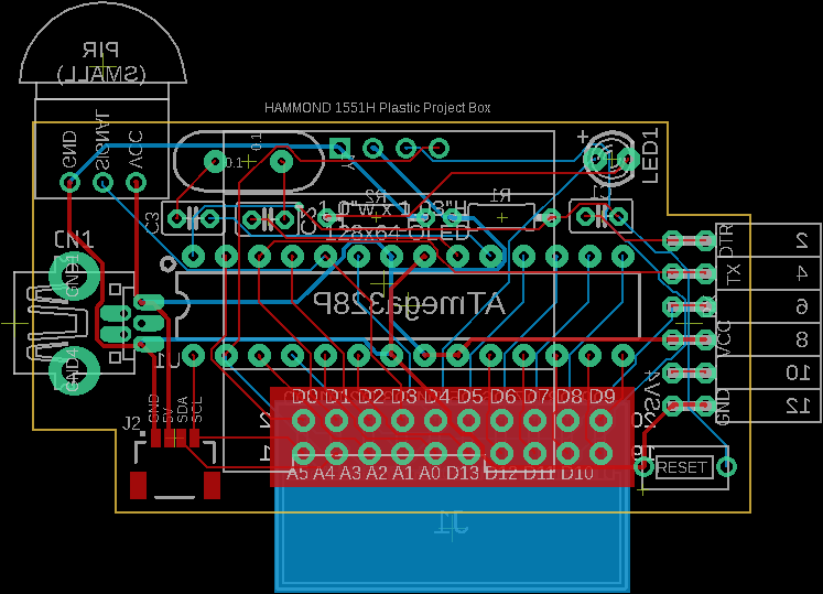
1Box Size
(Small)
Tiny SBC
Tiny SBC BOM
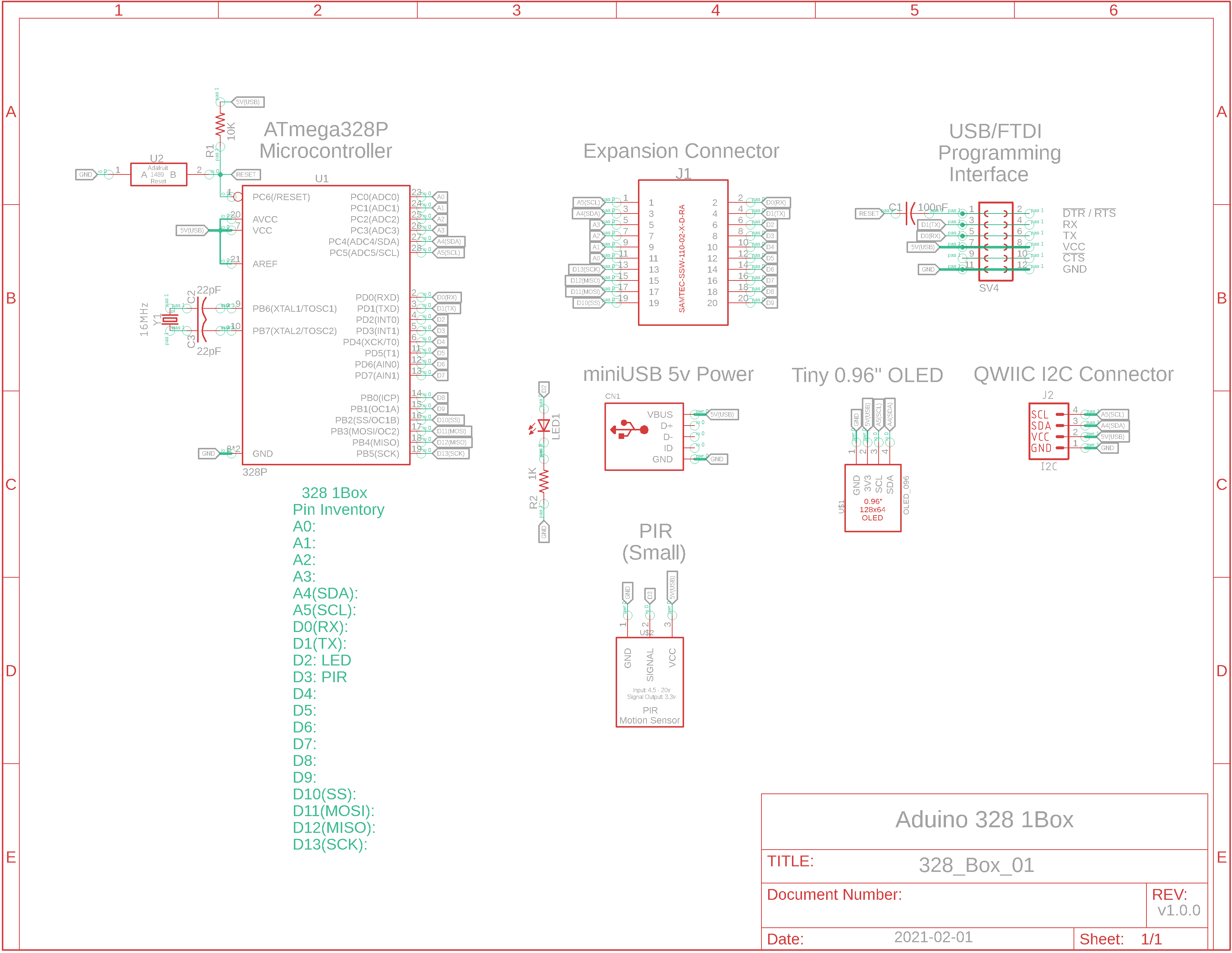
Sketch: WI_328_1Box.ino
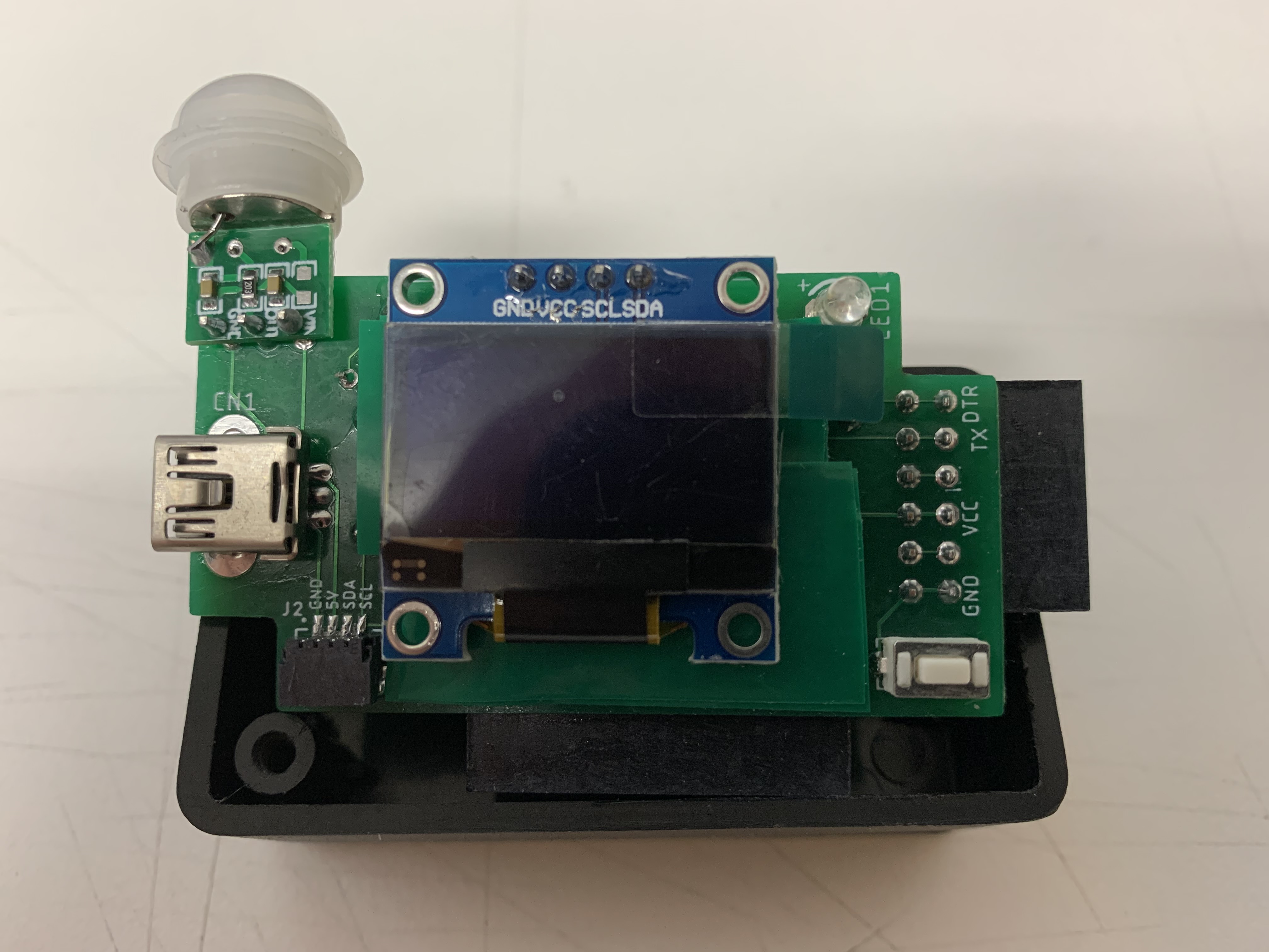
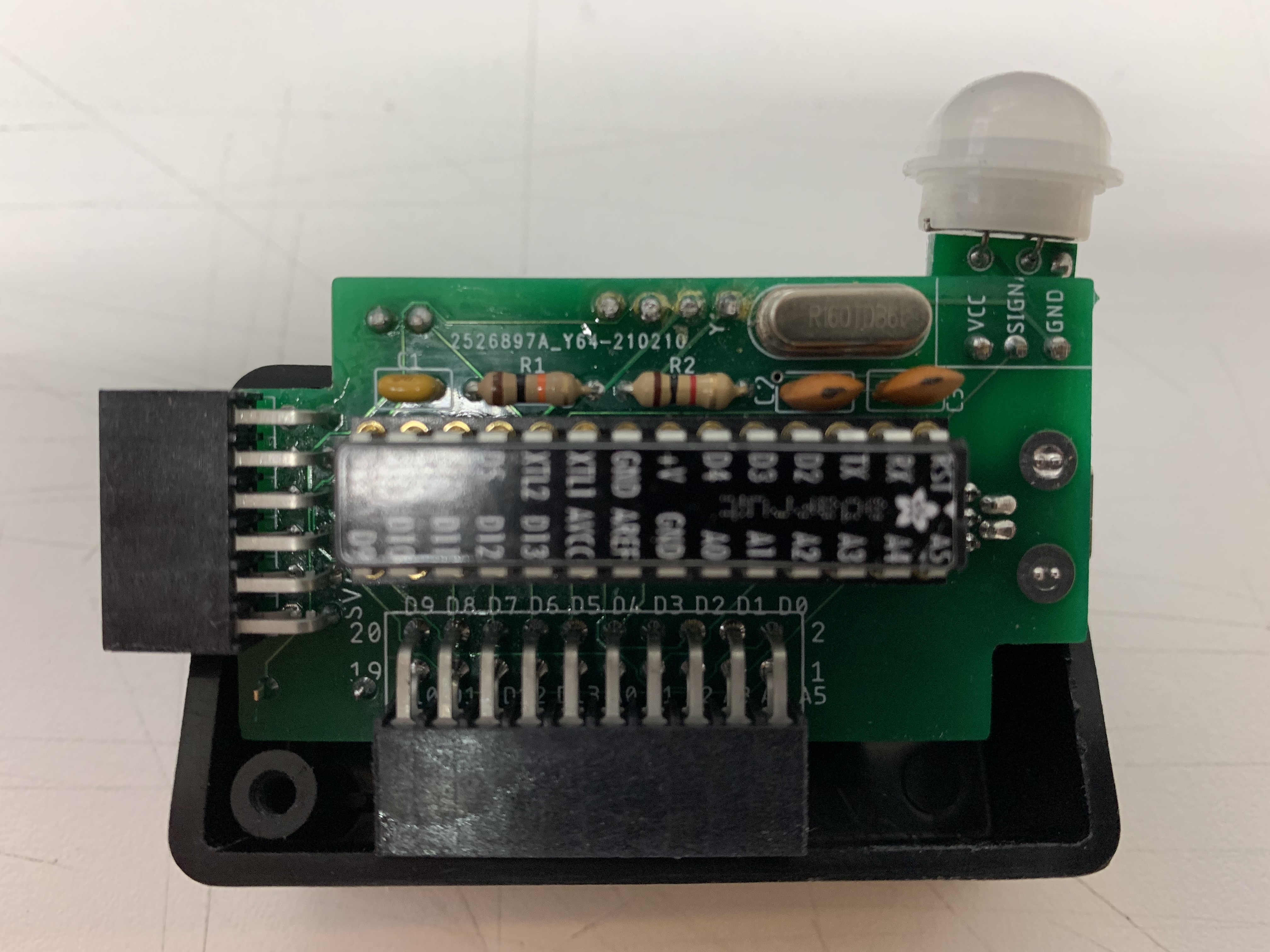
Tiny SBC
There was NO room for a BME280 sensor. This was an experiment to see how small an Aduino I could make. If you need to connect a BME sensor, you can use the QWIIC port or the front expansion connector.
Several features were removed due to lack of space. Note that the microprocessor can barely handle the program size, hence the reason the soft RTC was removed.
Remaining features include:
- ATmega328P uC
- 0.96" 128x64 OLED (I2C)
- PIR motion sensor
- LED
- QWIIC I2C connector for external I2C connections
- 20-pin female expansion connector
- miniUSB/FTDI programming port
- miniUSB power
Cube Board 1
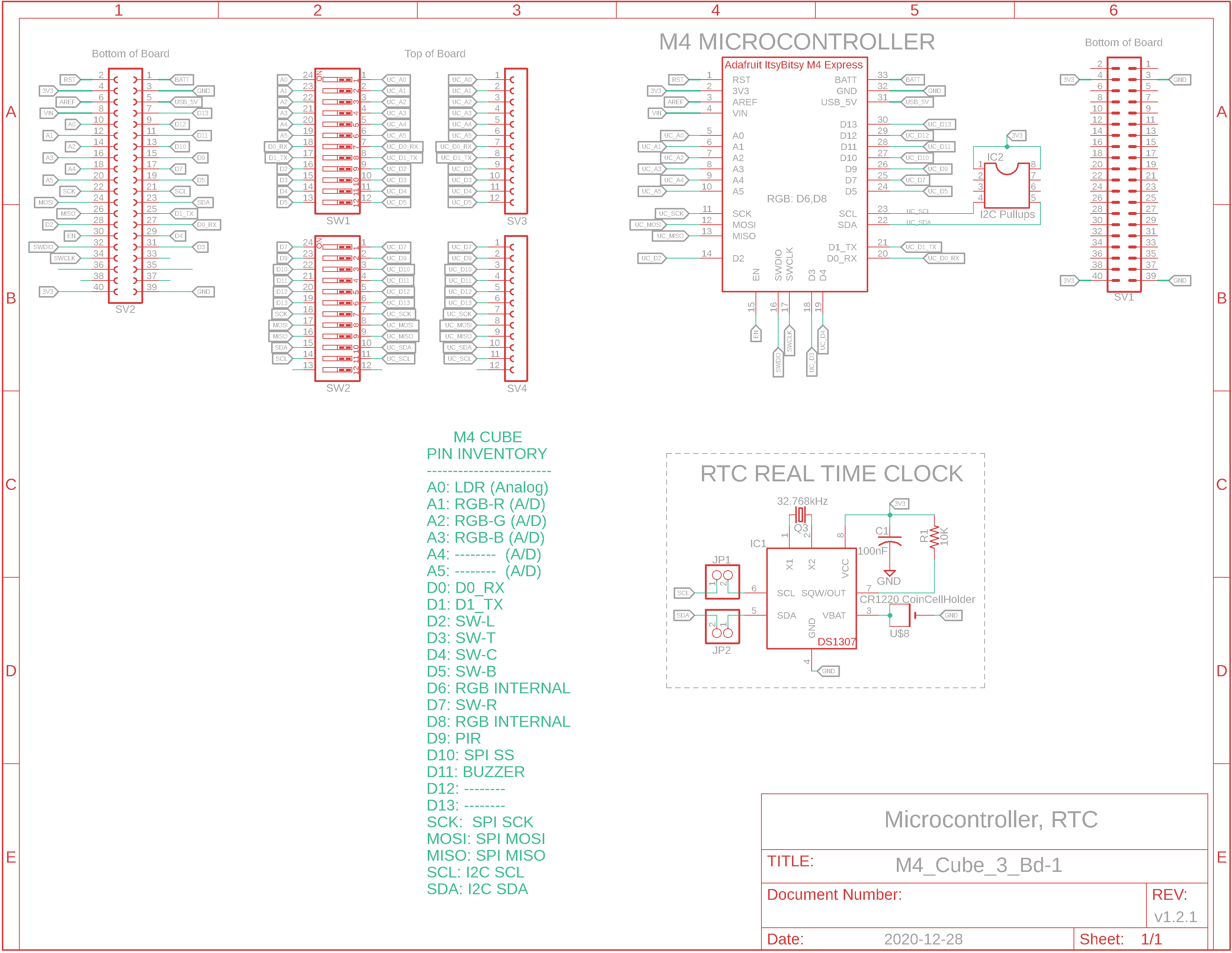

Board 1 BOM
Sketch: WI_M4_Cube_or_3Box__01.ino
Cube M4
This configuration has the most powerful microcontroller and the most features, and they are broken out for each board:
Board 1:
- Adafruit ItsyBitsy M4 module with SamD51 M4 microcontroller
- RTC with battery backup (I2C)
- swappable I2C pullup resistors
- 24 switches and female header to lockout out cube devices in favour of external ones
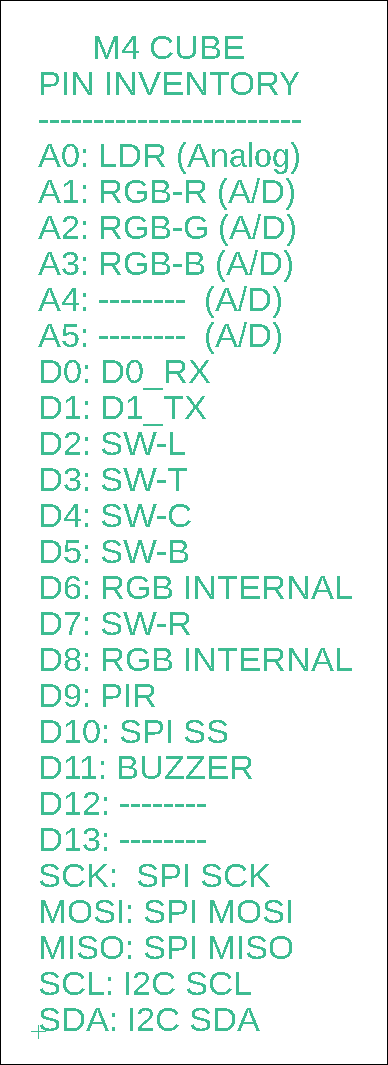
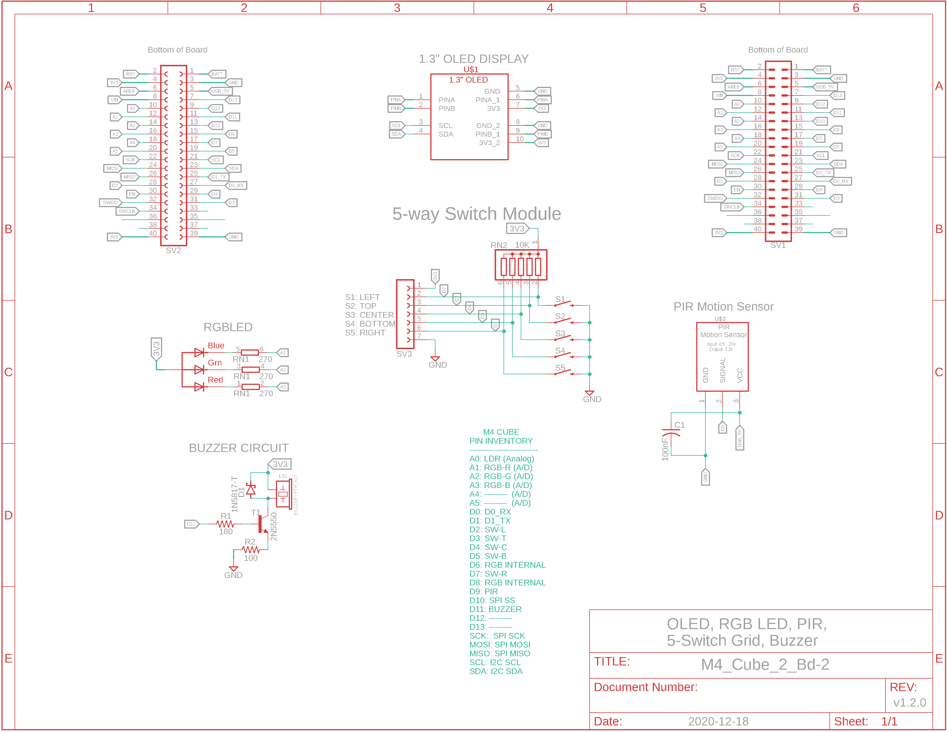
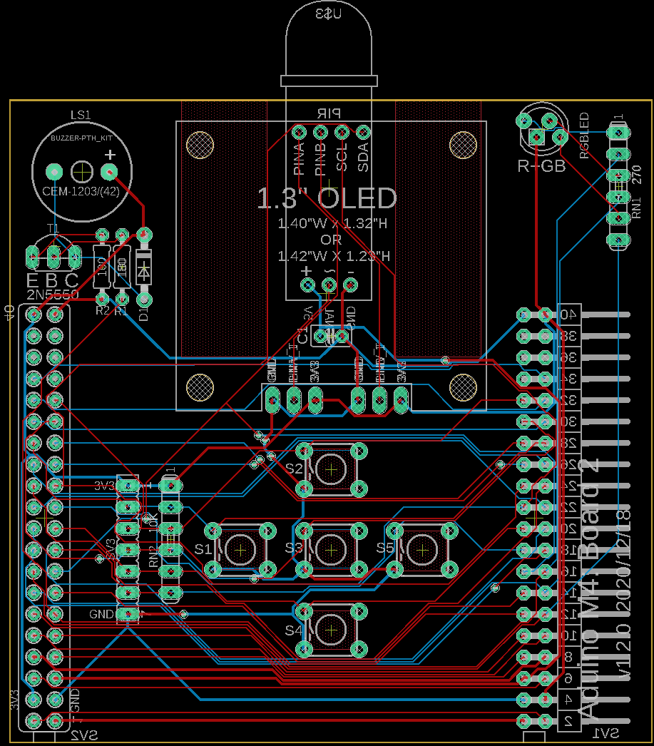
Board 2:
- 1.3" 128x64 OLED (I2C)
- matrix of 5 momentary switches (pulled up) with female external header
- PIR motion sensor (inside of board)
- Buzzer
- RGB LED
Board 3:
- BME280 temp/humidity/BP sensor (I2C)
- microSD (SPI)
- 3 power sources: barrel jack, mini USB, 2-wire screw terminal block
- JST I2C female receptable
- power switch and LED
- LDR with bias resistor
- large 4-character LED for quick view (I2C)
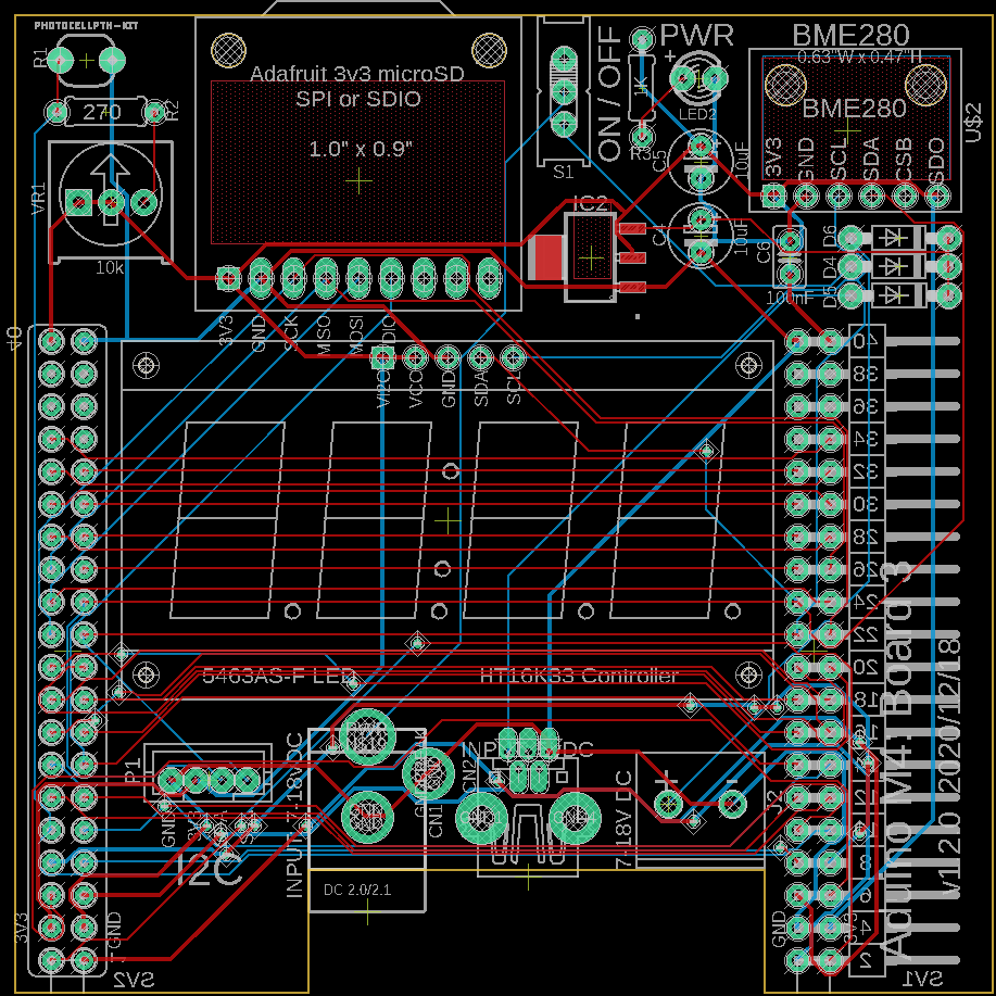
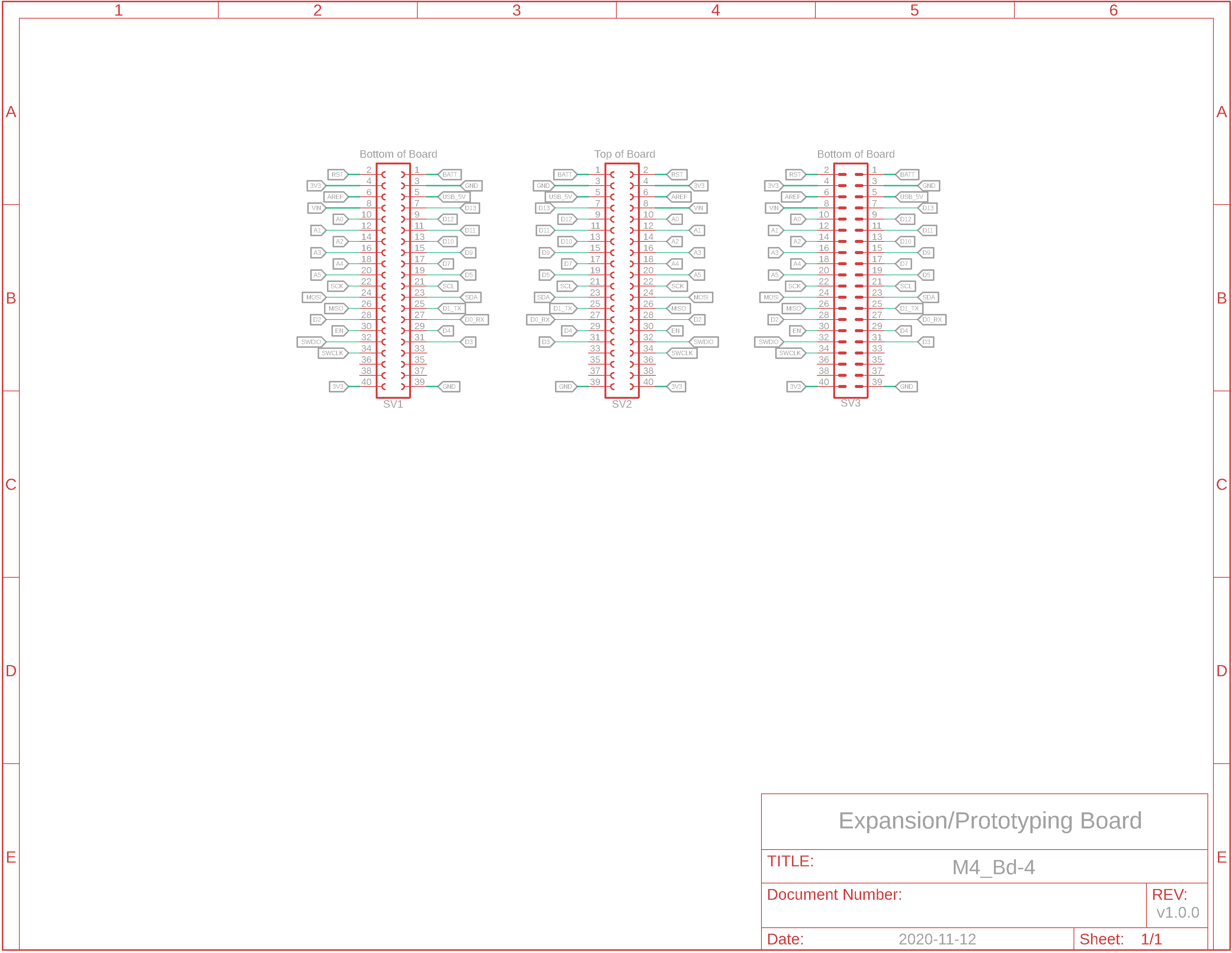
Board 4:
- 40-pin female expansion connector
- prototyping area
Cube Board 2
Board 2 BOM
Cube Board 3

Board 3 BOM
Cube Board 4
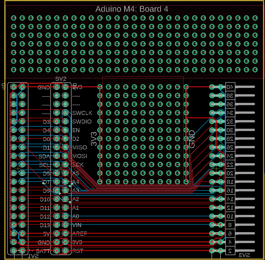
Board 4 BOM
Adafruit Feather M4 Express
MBC
(4Box Size)
Waiting on PCB fabrication...
M4 4Box 2.4" LCD Lower Board
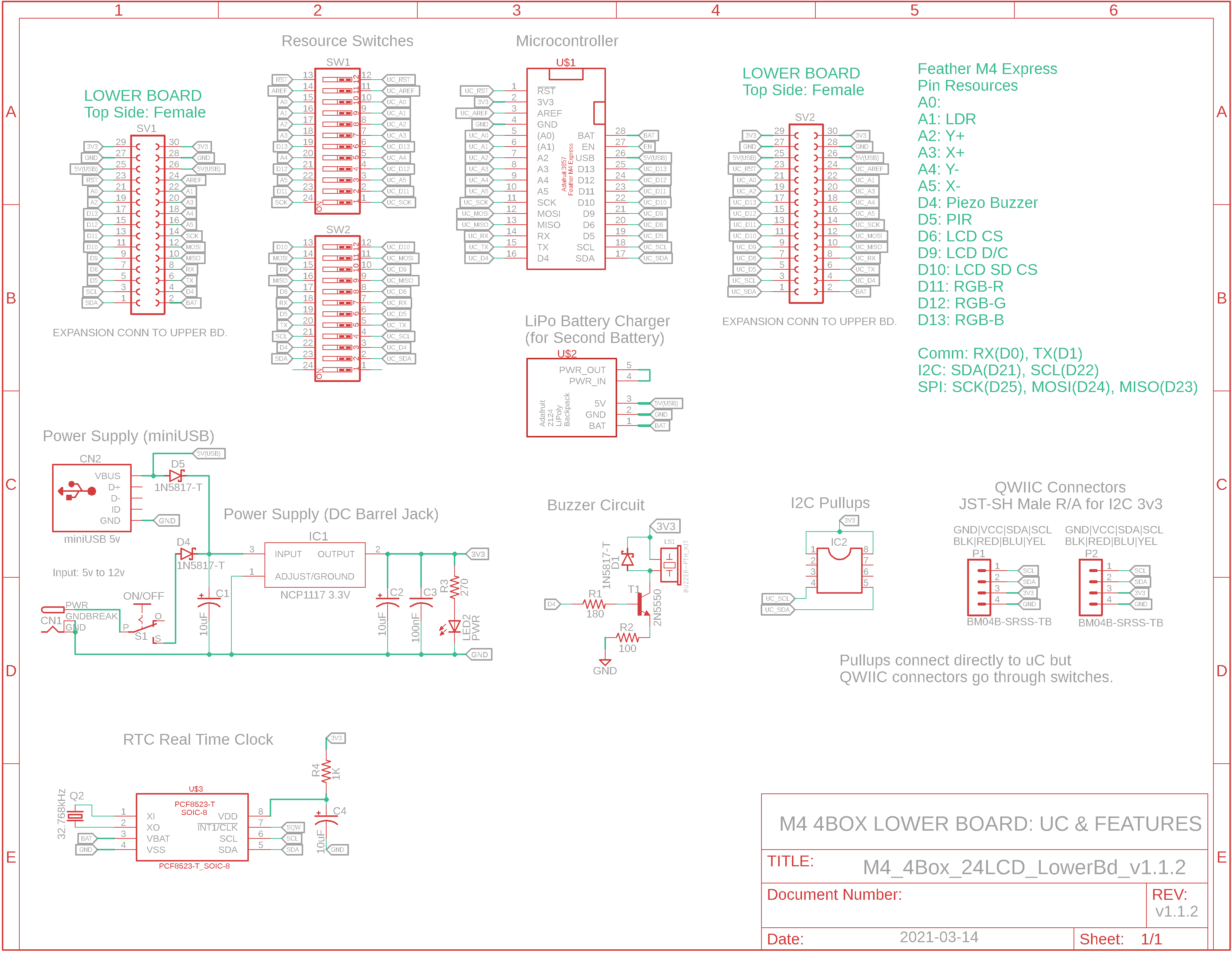
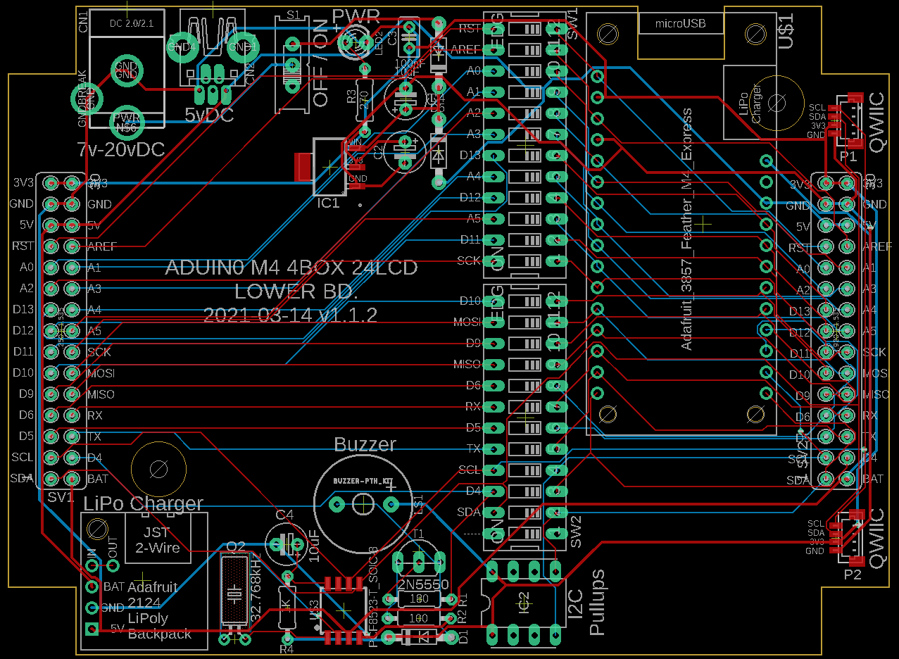
M4 4Box 2.4" LCD Lower Bd. BOM
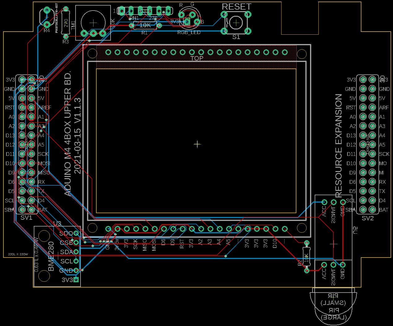
M4 4Box 2.4" LCD Upper Board
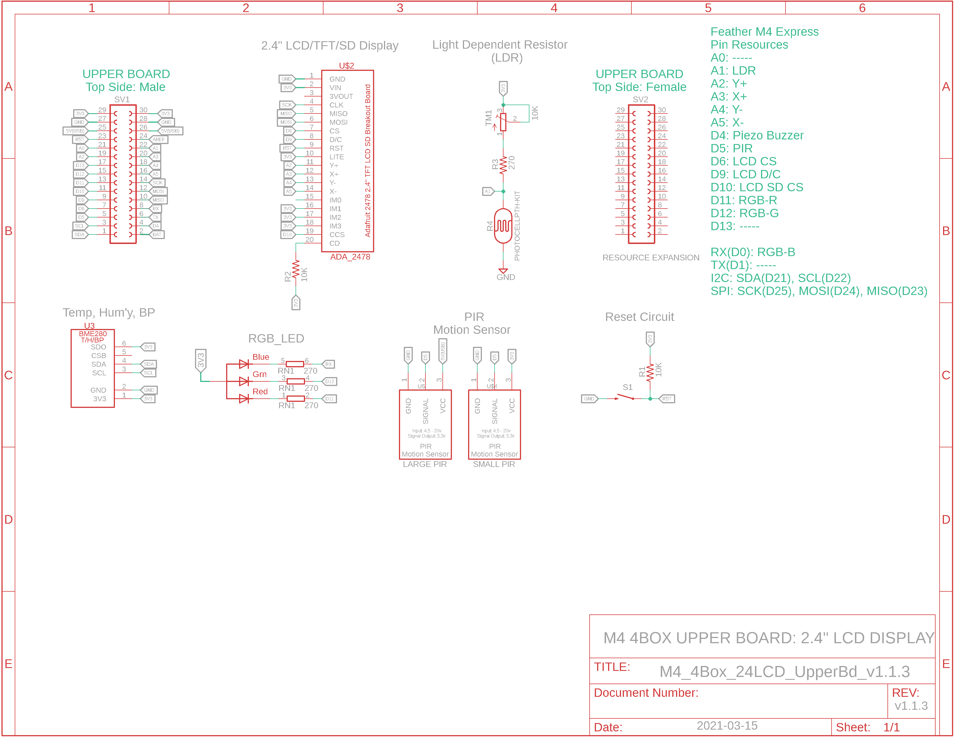
M4 4Box 2.4" LCD Upper Bd. BOM
Sketch:
This larger LCD system must be an MBC with upper (display) and lower (uC) boards.
I will post the assembled & running system when the latest revision of PCBs return from fabrication.
SBC
(2Box Size)
Back of PCB
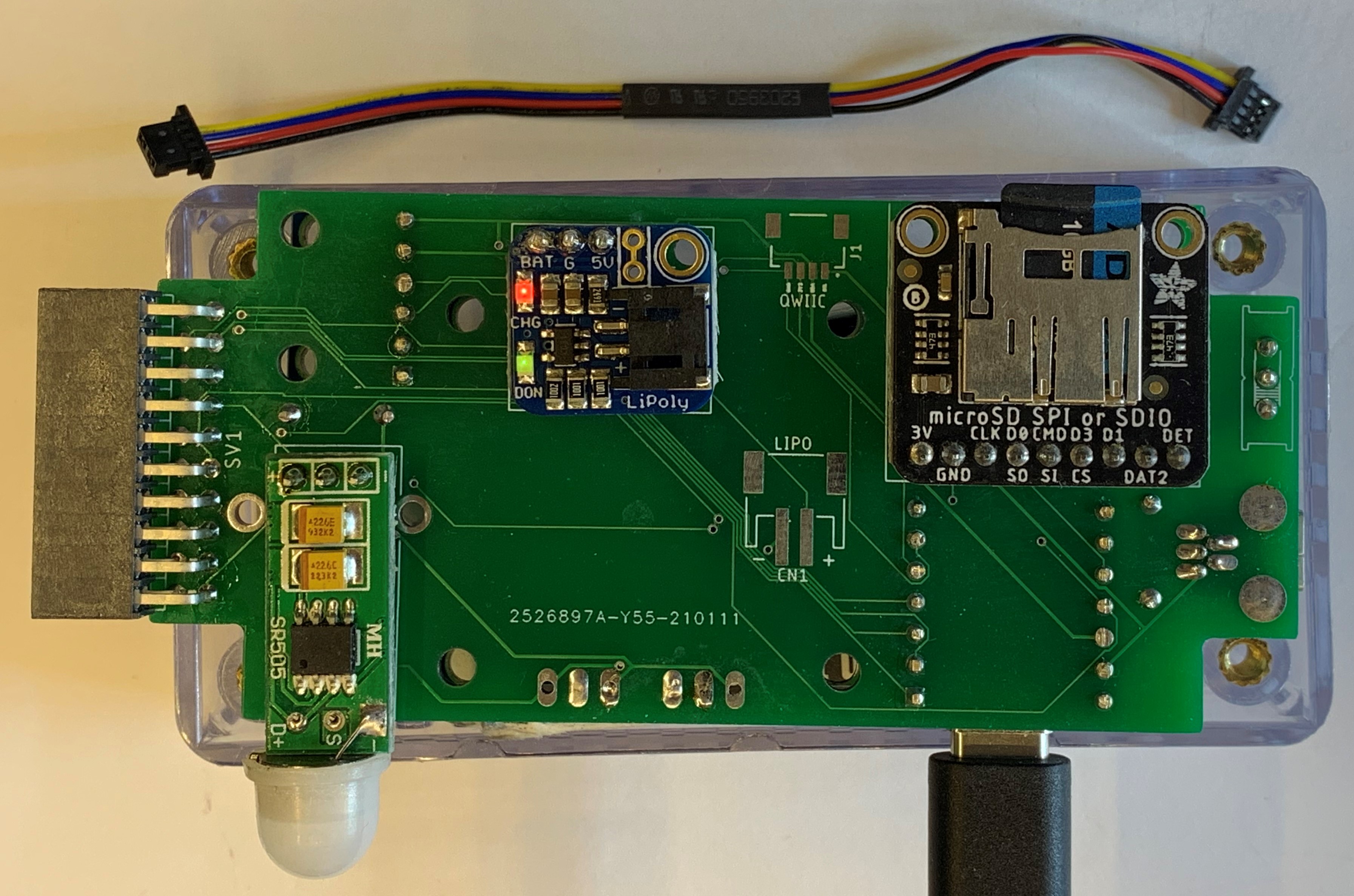
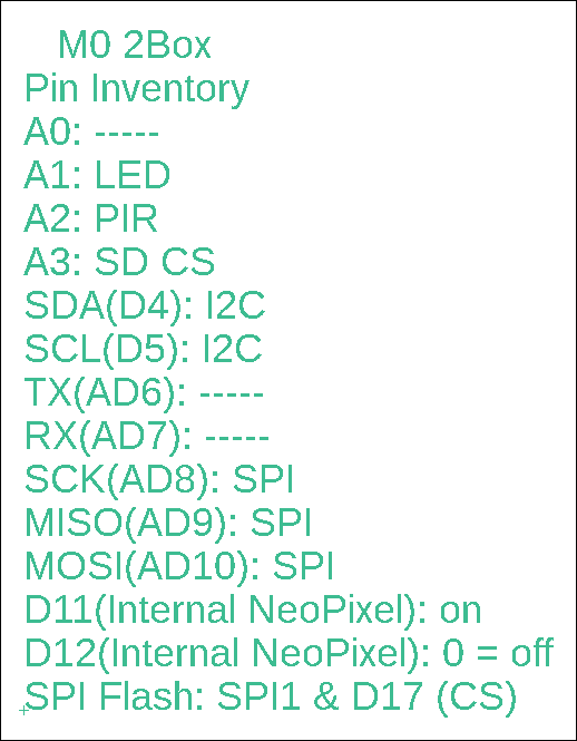
M0 2Box
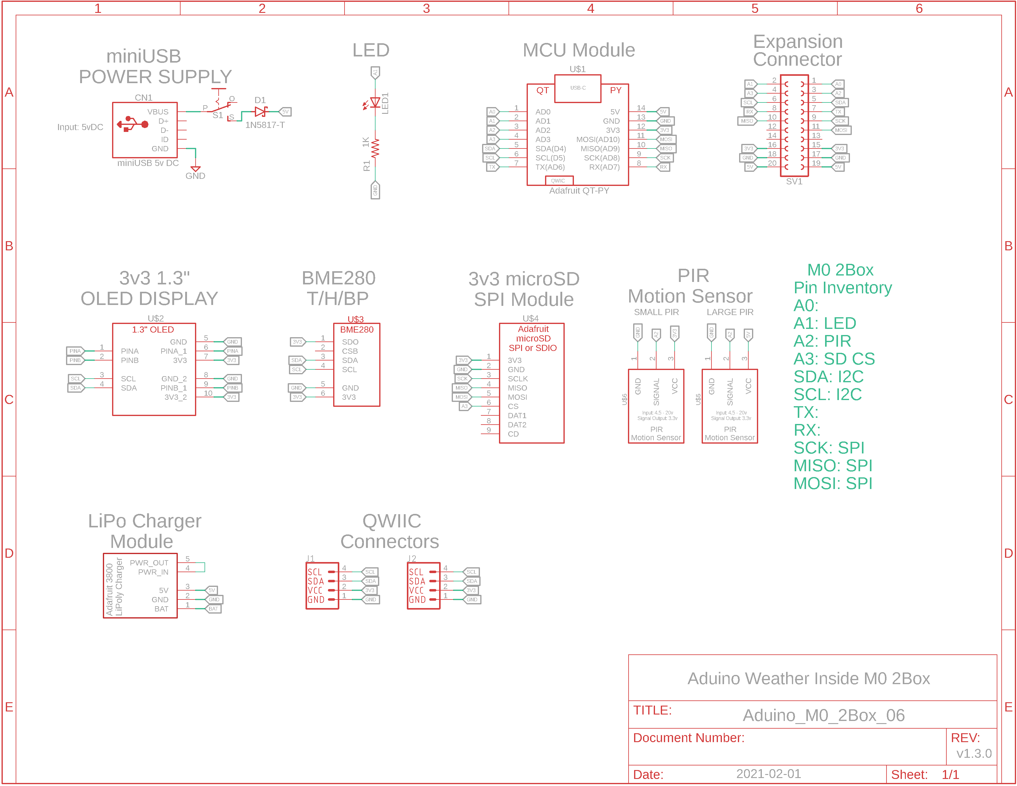

M0 2Box BOM
Sketch: WI_M0_2Box__Trend__q.ino
Features include:
- Adafruit QT PY M0 uC with USB-C
- 1.3" 128x64 OLED (I2C)
- miniUSB power, power switch
- PIR motion sensor
- BME280 sensor module (I2C, temp/humidity/BP)
- microSD module (SPI)
- JST I2C female receptacles
- LiPo charging module & cable
- 1000mAh LiPo battery
- LED
- Expansion connector
SBC
(1Box Size)
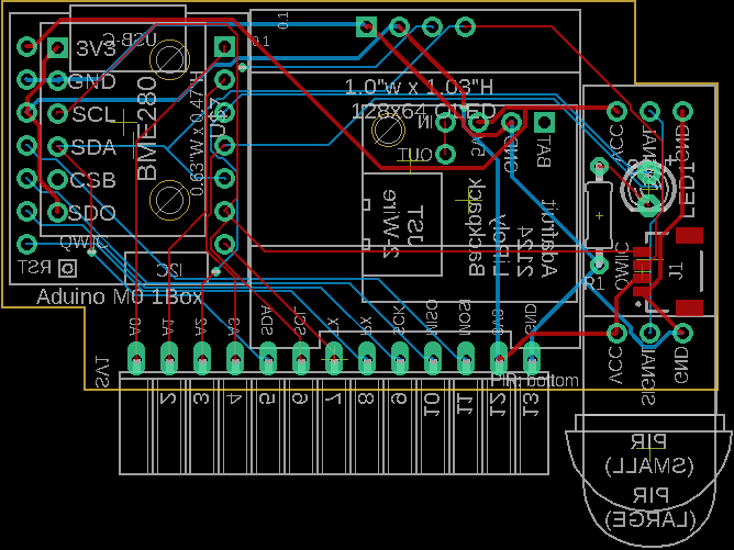
Waiting on PCB fabrication...
M0 1Box
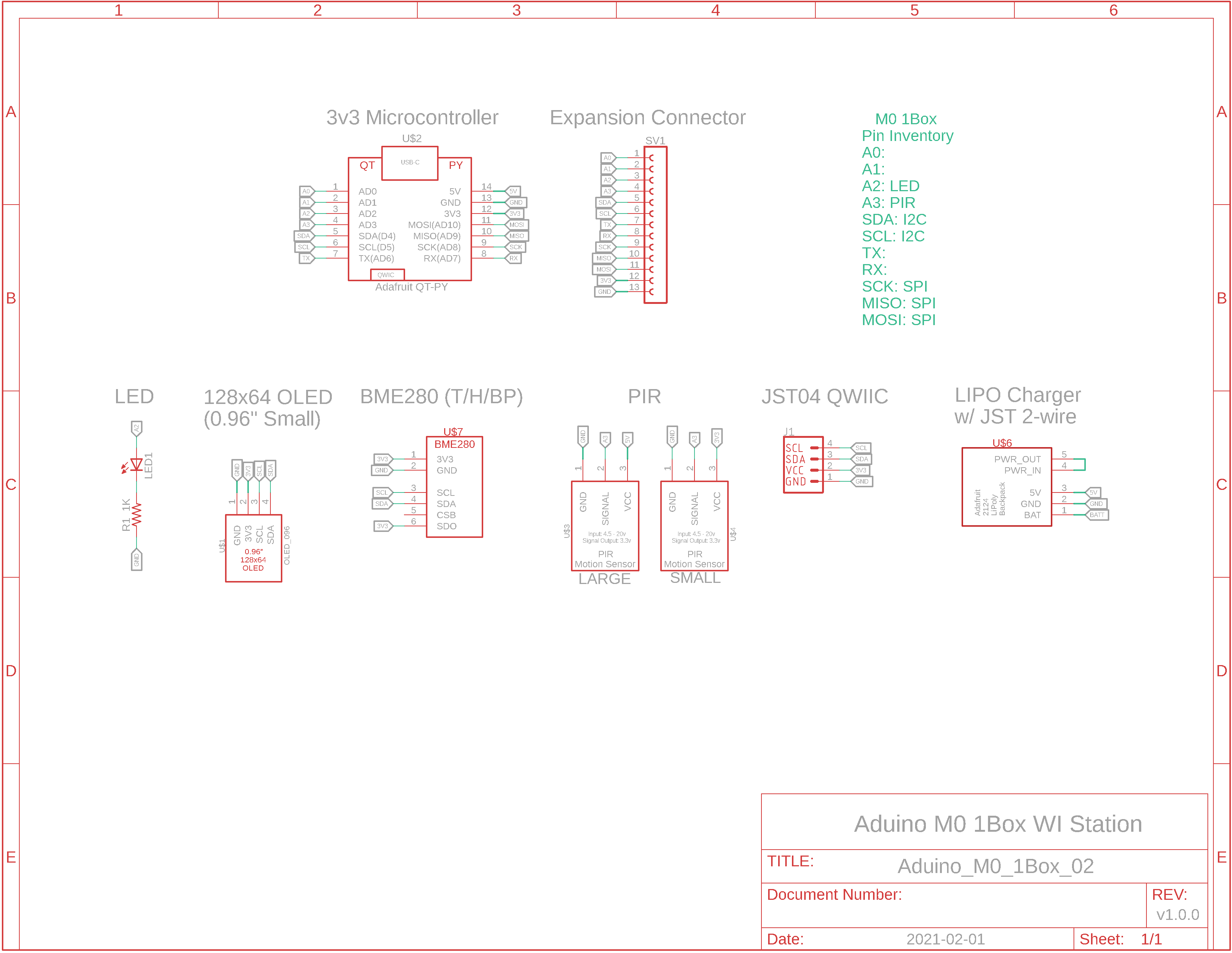
M0 1Box BOM
Sketch: WI_M0_1Box__01.ino

Because this is the smallest of the 3 Hammond boxes used with the WI system, it has the least number of resources. They are:
- Adafruit QT PY M0 uC with USB-C
- 0.96" 128x64 OLED (I2C)
- PIR motion sensor
- BME280 sensor module (I2C, temp/humidity/BP)
- JST I2C female receptable
- LiPo charging module & cable
- 600mAh LiPo battery
- Expansion connector