![]()
|
eZ8 Development Kits |
|
| TOPICS | NOTES |
|
Z8F64820100ZCOG utilizes a very powerful Zilog microcontroller, Z8F6482.
The Z8F6482 has 64KB of memory. The Z8F6082 has 60KB of memory and 128B of NVDS EEPROM-like memory. This is something you might want to consider for your project.
Zilog chose the Z8F6482 for the "ZCOG" development board. |
Dev Kit Must-Have Documents: Three documents are needed for reference with the ZCOG development board running the Z8F6482: - UM0263_(Z8F64820100ZCOG Z8 Encore XP F6482 Series Development Kit).pdf - RM0064_(Z8 Encore! XP® Board Support Package BSP API).pdf - PS0294_(Z8 Encore XP F6482 Series Product Spec [2018]).pdf
Other documents of interest are: - UM0128_(eZ8 CPU Core User Manual [2015]).pdf - PB0246_(F6482 Series General-Purpose Flash Microcontroller).pdf |
|
Z8 F6482 Series Development Kit
|
Z8 F6482 Series Development Kit To buy a "ZCOG": Arrow, Digikey, Amazon. Arrow is cheapest but their shipping charge is ridiculous.
COG Docs and recommended reading order: Product Brief (2017, PB0246) sales brief. Development Kit User Manual (2016, UM0263) development kit setup instructions, schematics, etc. API Programmer's Reference Manual (2019, RM0064) which includes board support package (BSP) application programming interface (API) with tons of software macros. General Purpose Flash Microcontroller Product Spec (2018, PS0294) The hardware peripherals "bible". Z8F6482 MCU Programming Spec (2015, PRS0019) Flash programming. eZ8 CPU Core User Manual (UM0128) Optional. |
|
Z8 Encore! XP F64xx Series Development Kit
|
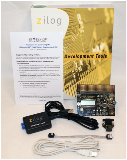
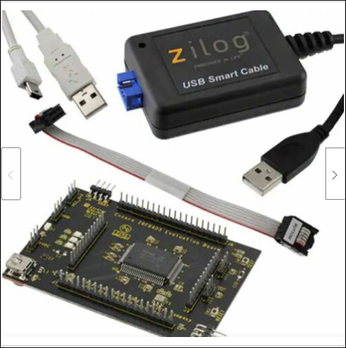
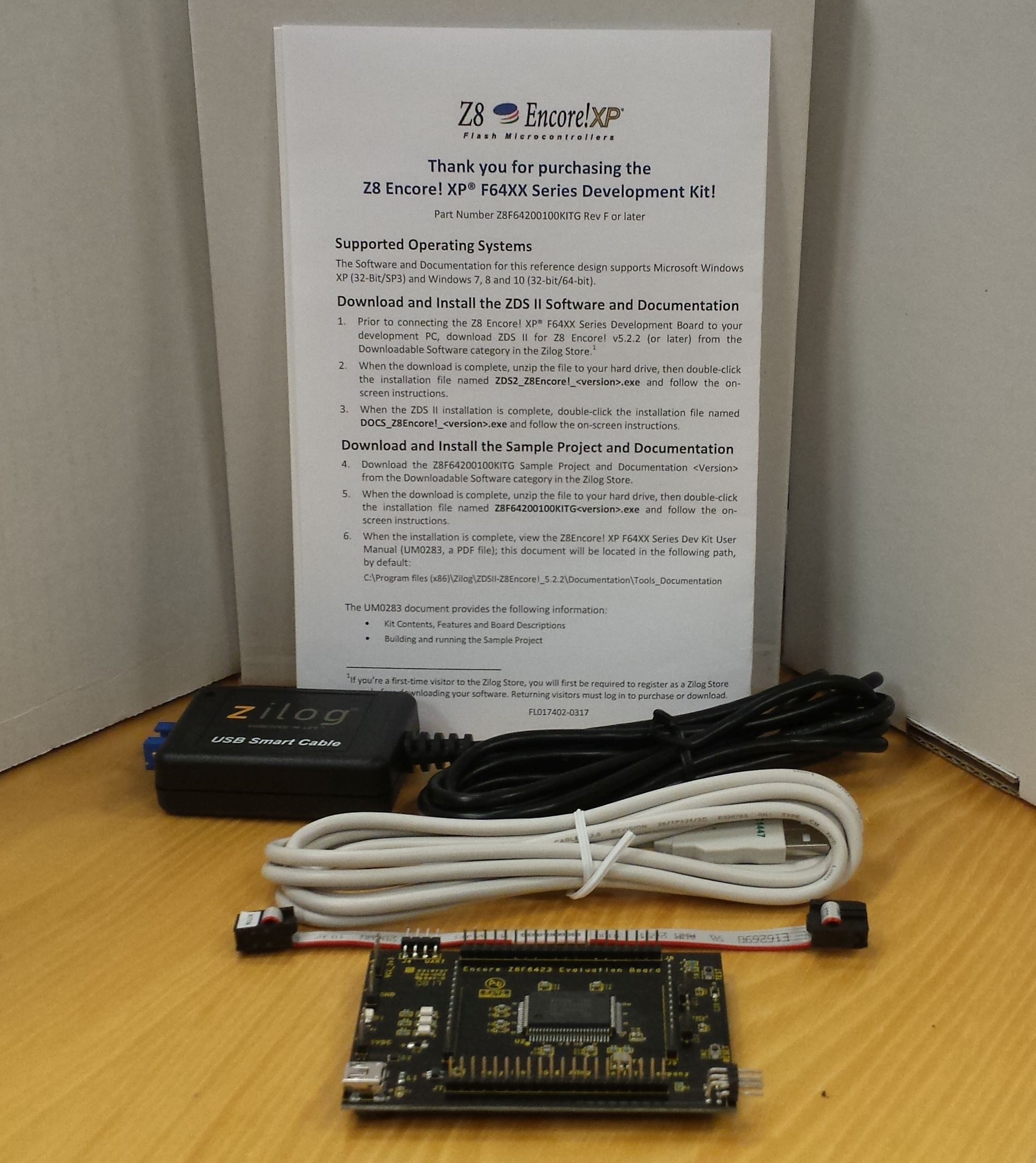
Z8 Encore! XP F64xx Series Development Kit To buy a "KITG": eBay, Digikey. eBay kit is cheapest and arrived within a week.
KITG Docs: Z8 Encore! XP F64xx Series Dev Kit (UM0283) eZ8 CPU Core User Manual (UM0128) Optional. ZDS Dev Studio User Manual (UM0130) USB Smart Cable User Manual (UM0181) |
|
GETTING STARTED WITH THE "ZCOG" DEVELOPMENT BOARD |
|
|
ZDSII and ZCOG Getting Started: 1 (ZDSII integrated development system, Z8F64820100ZCOG development kit)
|
Getting Started: 2 Read the first 11 pages of Development Kit User Manual (2016, UM0263). Don't connect any cables yet. We'll assume your host system is a Windows 10 PC and you'll use a powered USB hub with at least 3 free ports (miniUSB power for the dev board, USB Smart Cable, male 9-pin RS232 Serial-to-USB cable). You MUST use a powered USB hub or your PC won't see the dev board. Here's one I like: TP-Link UH720 7-port hub with 2 charging ports.
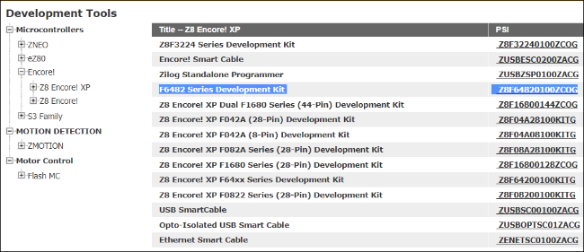
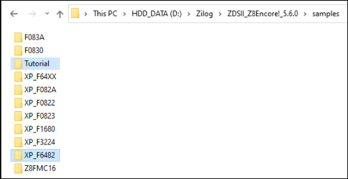
Install Zilog's IDE for the ZCOG: At the opening page to www.zilog.com, choose menu item Tools and Software | Development Tools. From the left vertical menu, choose Encore! under Microcontrollers. Now select Z8 Encore! XP. You may have to click it twice to get it to populate the right panel where there should be about a dozen items. Select F6482 Series Development Kit Z8F64820100ZCOG. That will present you with a page describing the ZCOG kit and a list of documents you should download. In the middle of the page is a link to the free ZDSII IDE software, BSP board support package source code and sample programs; select the Download the following free software link. Open the topmost link, Zilog Developer Studio II, and select ZDSII - Z8 Encore!. The latest code as of 2021-08-26 is v5.6.0; click the link on the right. Click View and Accept Software License so you can download it; it's about 25MB. Stick it in your BIN folder or wherever you keep installation or Zip files and then run it to install the IDE (integrated development environment). I install mine on D:\ so the installation path ends up being D:\Zilog\ZDSII_Z8Encore!_5.6.0. You'll also be prompted to install the SmartCable driver software: do it. The ZDSII IDE will open up. Shut it down for now.
Explore a little: If we go back to the samples folder, we could create a new folder called Tutorial that we'll put our code in later. Now that the ZDSII IDE and cable are installed, we can move onto the next step - testing your dev board. Note that we have not connected the board and cables yet. |
|
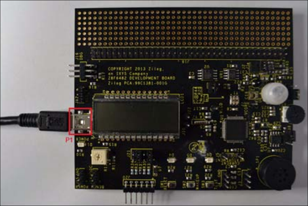
Getting Started: 3 Plugging Cables: According to page 6 of UM0263, the dev kit user manual, once the IDE software is installed, you should double-check the state of all of the black jumpers on your board.
Next we should connect one end of the ribbon cable with the label "BOTTOM" on the bottom of the cable to the dev board and the other end to the USB Smart Cable. Windows was provided with the drivers during the ZDSII installation so if should find it when you plug the cable into your host PC. My path to the drivers in case Windows 10 did not find them is D:\Zilog\ZDSII_Z8Encore!_5.6.0\device drivers\USB\USBSmartCable\USB\x64. With the cable plugged in on both ends, the amber LED in the top left corner of the front of the plastic housing will be illuminated when we plug in the dev board power - the miniUSB cable. Plug the miniUSB cable into the board and into the charging port of your powered USB hub. The dev board's POWER LED should now be illuminated.
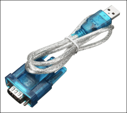
The last step is to attach a male 9-pin RS232-to-USB cable to the little female RS232 interface board that you will in turn attach to the dev board. Here's a link to one from Banggood.com that works. The other end of this serial cable is plugged into your powered hub, of course. Once we have a program compiled and running on the ZCOG, you'll be able to see the serial stream the cable is conveying.
|
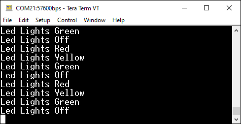
Getting Started: 4 Setup your terminal emulation software: The project code we'll load soon requires the use of a serial terminal for the ZCOG to communicate with the host PC. For all of my development time on the Z80, I've had good luck using TeraTerm terminal emulation software. Here is a link to the .exe file. If you are uncomfortable downloading this executable from my website, Google teraterm v4.99 and download it from a trusted site. Once installed (on your D: drive I presume) right-click This PC on your desktop and click Manage. Then click Device Manager, and open Ports in the adjacent panel. When you disconnect the RS232-USB cable from your hub, the port should disappear. Note it and replug the cable. Close Device Manager. Within TeraTerm, navigate to Setup | Serial Port, choose your newly discovered serial port, and configure the rest of the choices to Speed 57600, Data 8 bit, Parity none, 1 Stop bit and Flow Control none. Click OK but before you do anything else go back into Setup and select Save Setup. Accept the default name of TERATERM.INI unless you plan on running several different configs, in which case each will need their own unique filename. The result once you get the "blink" program running should be the same as you're seeing in the screenshot below. That's what we'll do next.
|
|
Getting Started: 5 Startup ZDSII and Select your Project:
We're returning to page 8 of
UM0263. Click the Windows 10 Start button
Within ZDSII, click File | Open Project and choose the ledblink.zdsproj file. If you're not seeing it, navigate the Look In: dropdown box to D:\Zilog\ZDSII_Z8Encore!_5.6.0\samples\XP_F6482\XP_F6482_LedBlink_C to locate and select the file. In the left panel you should see all of the Standard Project Files that comprise the project.
Select your Debugger: Before we compile and send the result to the board, ZDSII needs to know a little more about the recipient. Under the top menu item Build, choose Set Active Configuration. At the top of your screen Debug should be visible. In the top menu item Project, select Settings. From the left navigation panel, choose Debugger at the bottom if it's not already selected. In the upper right panel, you want to click on the "ZCOG". In the lower right panel, choose USBSmartCable for the Current Debug Tool. If you click on Setup beside the cable, it should provide you with its Serial Number. Now you know the cable is talking to both ends. And finally click OK.
Build your executable file: Next we need to compile these source files into an executable file that can be downloaded to the microcontroller. Under Build at the screen top, click Build and then Rebuild All when Build completes. There should be no errors in the bottom panel.
Download and Execute the file: Under top menu item Debug, click Go. Alternatively, you could click Connect to Target, followed by Download Code. There should be no errors in the bottom panel. A small window will pop up showing the progress of the download. If you receive a warning of "The silicon (B) on the target board is not the latest revision (C) supported by this release of ZDSII.", close the warning then unplug and replug the cable. You're only performing the latter if the board appears hung. Things should be working again. |
Getting Started: 6 Summary You have opened a project containing all required files to create an executable file for your dev board. You built the file, rebuilt it, and downloaded it to the Z8F6482AT024XK chip. To test the program, observe the Red, Amber and Green LEDs flashing sequentially. Touch the switch above either the Green LED or the Amber LED and the sequential order of flashing reverses. Touch the switch above the Red LED and all three LEDs flash together before the sequential flashing continues. With TeraTerm terminal emulation software running on your PC, the LED flashing actions should be reflected in text on your screen. Below is short video of successful operation. Click the .gif file for a larger .mp4 file.
Click the .gif for a larger .mp4 video
You have tested your ZCOG and are now ready to write some code. Hit the HOME button below and proceed to eZ8 Programming. |
![]()