|
CIRCUIT 1-2: CPU System Clock(s) |
| Name | Circuit Schematics (click to enlarge) | Info |
|
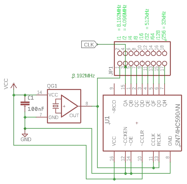
CPU Clock Frequency Divider
(Bill of Materials)
|
Eagle CAD: Clock Frequency Divider Eagle CAD: Clock Frequency Divider Simplified
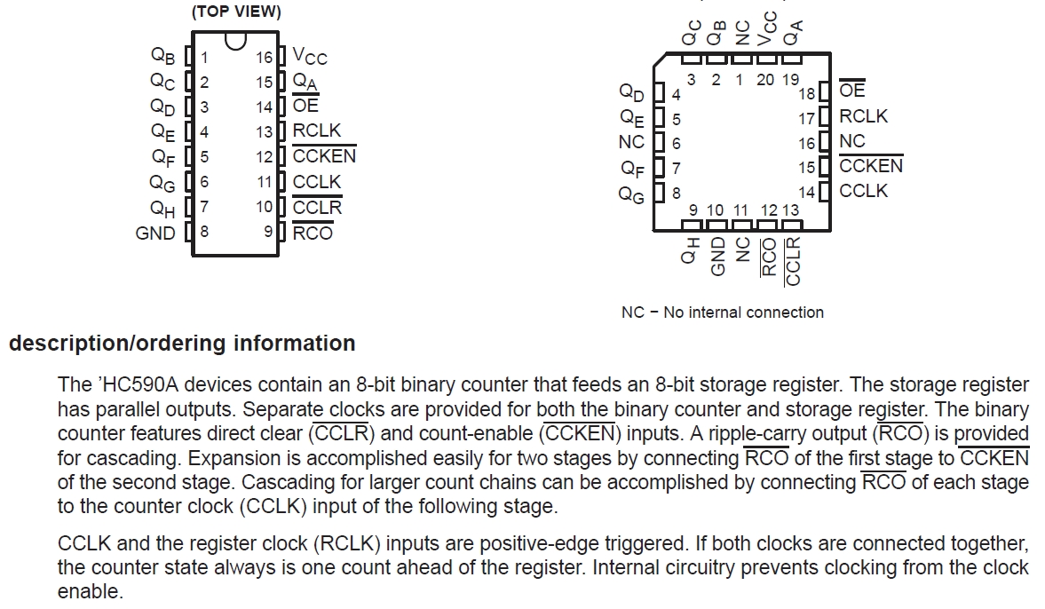
74hct590 8-bit Binary Counter
|
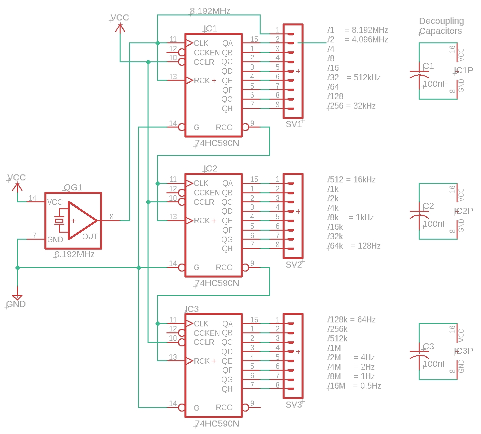
Using a crystal oscillator and a 74590 to set the CPU clock frequency The top-most adjacent circuit is not a true variable CPU clock because it uses numerically declining samples of the crystal oscillator frequency to provide CPU clock, i.e., 8MHz, 4MHz, 2MHz, etc. You will have to manually jumper the speed you want to use. It will however meet most of our needs. In the adjacent top schematic is an 8.192MHz crystal oscillator attached to pin 11 of the top '590. Each output of this '590 divides that signal by 2. At the last output, pin 7 of the first '590, the signal has been divided by 256 so it's now 32kHz. The Ripple Carry Out (RCO), pin 9 of the first '590, is attached to the Clock input pin 11 of the second '590. It's first output, pin 15, again divides the signal by 2 so it's 16kHz. The RCO of the second '590 is attached to the third '590 on pin 11, its Clock. Now its frequency is down to 64Hz. By the time we get to pin 7 it's only 0.5Hz so each CPU cycle is 2 seconds long. You will need a speed of about 500Hz if you decide to build and test the 8255 I/O circuit later. You will need a speed of 4MHz to test the LCD panel if you decide to build and test it, too. If you have stability issues with your configuration, check to ensure CCLR is pulled high on all 3 devices. The CPU clock signal speed you choose is simply wired/jumpered from one of the 8 possible '590 outputs to pin 6 of the Z80.
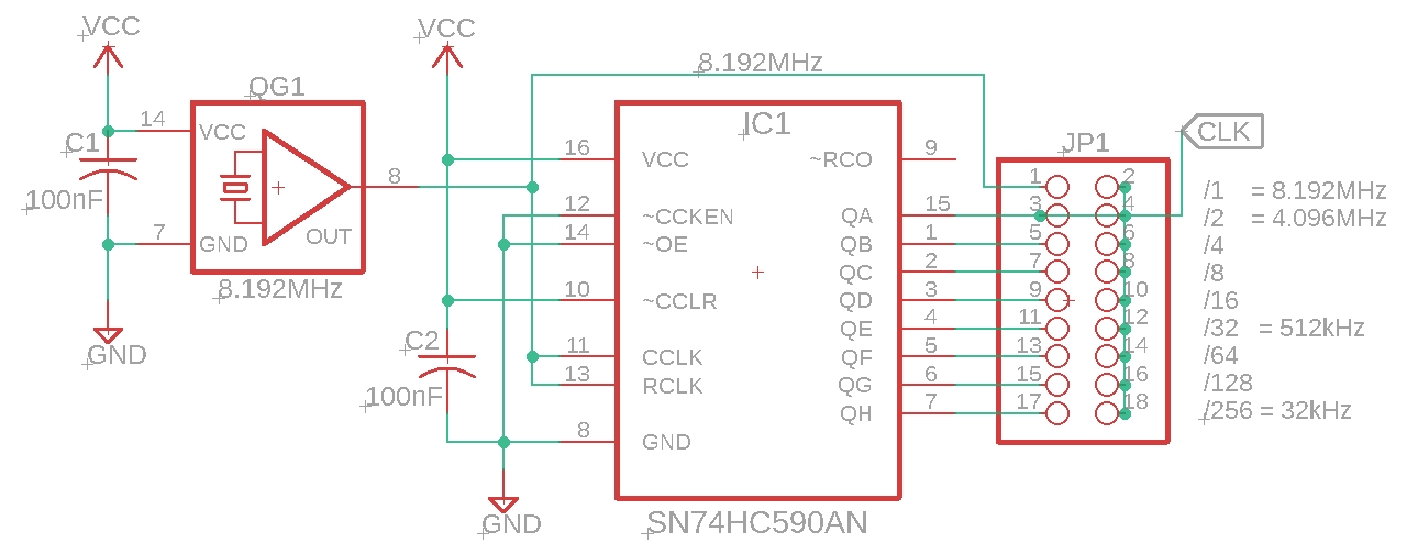
Adjacent is a simplified version of the circuit with one '590 you will probably want to use if you have a need to try various clock speeds with one crystal oscillator.
Alternatively, you could just use the crystal oscillator by itself. However you will lose the ability to use the 2MHz jumper to connect the UART. We have not covered this yet, but the best crystal value for the UART is 1.8432MHz. That's because the crystal speed must be decided by a sampling rate of 16 before you choose your baud rate. Example: 1.8432M / 16 / 9600bps = 12. This is the value you would plug into of your UART's config register to select a baud rate of 9600bps. Let's try a 4MHz crystal divided by 2 to 2MHz, divided by 16 sampling rate, then divided again by a baud rate of 9600bps. The selector value would be 13.02. It is so close to 13 that we could successfully use it. So that means with an inexpensive '590 and one crystal oscillator we could feed two circuits - the CPU and the UART; we would not have to buy a second oscillator. Something to think about with your design. |
|
CPU Variable Slow Clock, 4MHz Clock |
Eagle CAD: Slow/Fast Clock
|
This is kind of a cool CPU clock in the sense that a jumper determines whether it's a slow (1Hz to 100Hz) clock or a much faster 4MHz clock. JP7 is the jumper you use to select either the variable slow clock or fixed high-speed clock. Adjust the potentiometer, VR1, to set the speed from 1Hz to 100Hz. Want to go slower? Increase the size of the capacitor C7. Faster? Decrease its size. More fine control? Use a multi-turn potentiometer. VR1 can go down to 0 ohms and cause a short hence the reason for R3. |
|
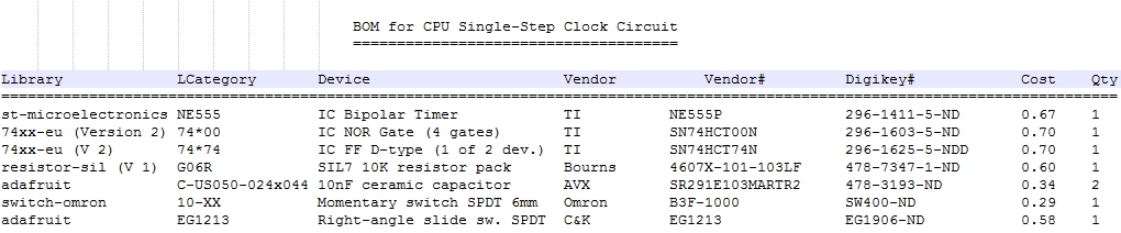
CPU Single-Step Clock & Programming an EEPROM
(Bill of Materials)
|
Eagle CAD: CPU Single-Step Clock
|
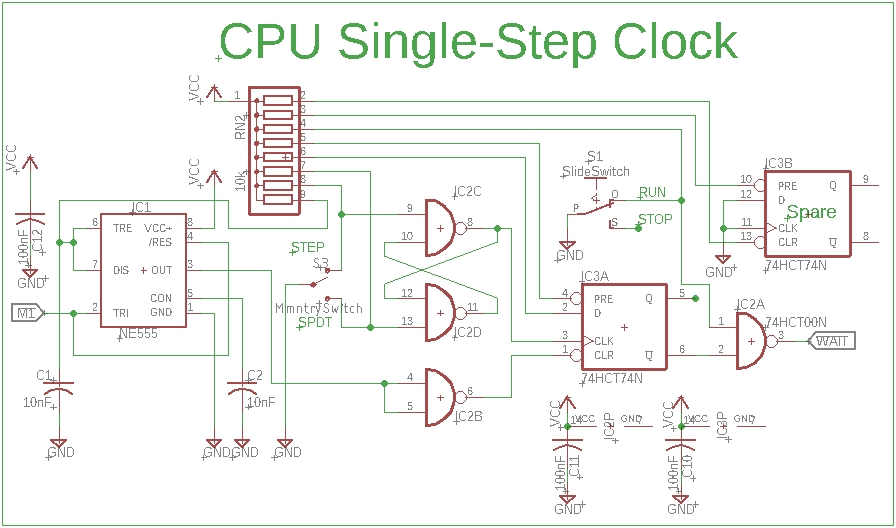
This CPU clock circuit uses the M1 and WAIT control signals (see page 5 of the Z80 manual) to single-step the CPU, and requires much fewer components than the Single/Multi-step circuit below. Its speed is determined by the RC circuit of the 555 timer and how fast you can press the Step button.
Note: Z80 control signal M1 is only asserted at the beginning of an instruction, not for every byte operand that is to be read or written. Therefore, you will not see everything that transpires in your Z80 program - only the leading instruction.
Test Your Circuit Visit CPU Single-Step Clock Test to test your circuit. There is also a video on how to program your EEPROM for the test. |
|
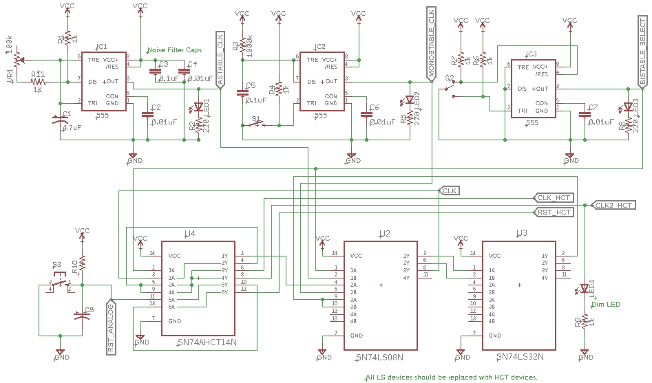
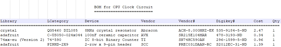
CPU Single/Multi-step Clock
(Bill of Materials)
|
Eagle CAD: Single/Multi-step CPU Clock
|
OPTIONAL: This CPU clock circuit contains both a multi-step circuit and a single-step circuit for the Z80. The CPU Reset circuit used in the adjacent "frame" is included as part of the schematic. You can build the variable clock circuit using these four Ben Eater videos and parts list found here. Replace the LS devices with HCT devices if you`re connecting to the newer CMOS version of the Z80 CPU, Z84C00xx. There are two output signals, CLK_HCT and CLK2_HCT, the former you`ll connect to the Z80, and the latter is used to drive an activity LED because we don`t want to load down the CPU at all - it has a very "tight" current budget. |

![]()