|
CIRCUITS 1-5: Bus Monitor(s) |
| Name | Circuit Schematics (click to enlarge) | Info |
|
CPU Bus Monitor: Bar Graph LEDs
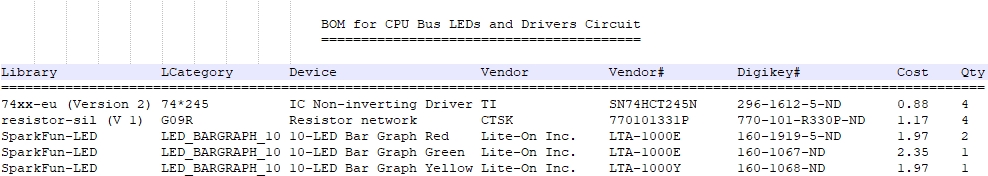
(Bill of Materials)
|
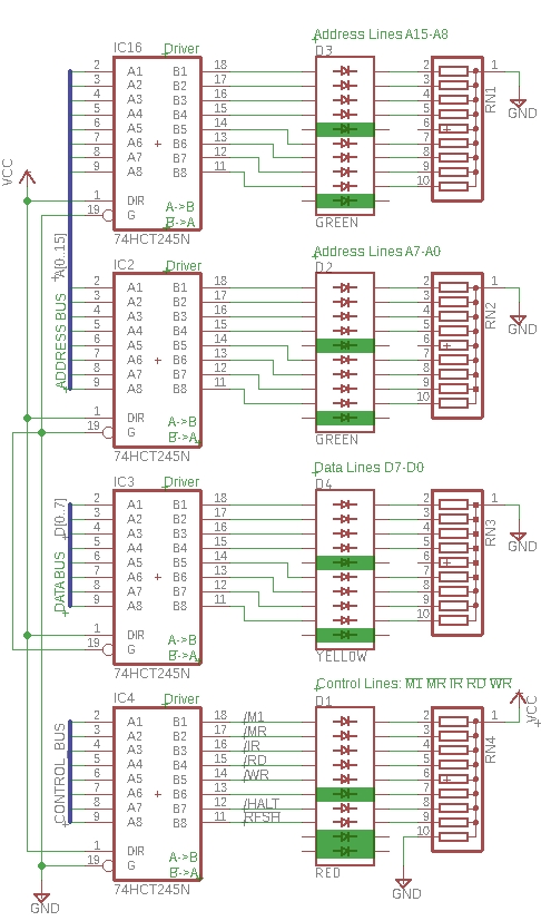
Eagle CAD: Signal Drivers and LED Bar Graphs
|
This circuit will display the address, data, and control lines to bar graph
LEDs. The adjacent schematic shows 74HCT245 drivers being used to drive the Bar Graph LEDs. (The HCTs are a better match to the CMOS Z80 CPU (Z84C00xx) than LSs.) Maximum Z80 CPU current drive varies with its posted speed. See below for specific values extracted from Zilog`s Z80 Z84C00xx CMOS Product Specification. If we assume 50mA maximum, every effort should be made to keep current requirements low. Connecting almost 30 LEDs to the address, data, and control bus lines with each requiring 10mA of current will easily exceed the limit and cause erratic CPU operation. It will overheat and probably fail. Electrical Specifications: Page 34 of ps0178.pdf; earlier .pdf versions see page 30. Z80 CMOS version: 4.5v to 5.5v voltage supply. NMOS version: 4.75 to 5.25v. Output low voltage max: 0.4v Output high voltage min: 2.4v Input low voltage max: 0.8v Input high voltage min: 2.2v Z84C00xx CMOS CPU power supply current (max): 4MHz = 20mA, 6MHz = 30mA, 8MHz=40mA, 10MHz=50mA, 20MHz=100mA. Z8400xx NMOS CPU can handle 200mA of power supply current (see page 37 of ps0178.pdf), substantially more than the CMOS CPU. Unused low-active signals like NMI, BUSRQ, etc., should be tied high with pull-up resistors. Practical values range between 4.7K (1mA) and 10K (0.5mA). My personal choice is 10K for pull-ups and 4.7K for pull-downs. |
|
CPU Bus Monitor: 7-Segment LEDs
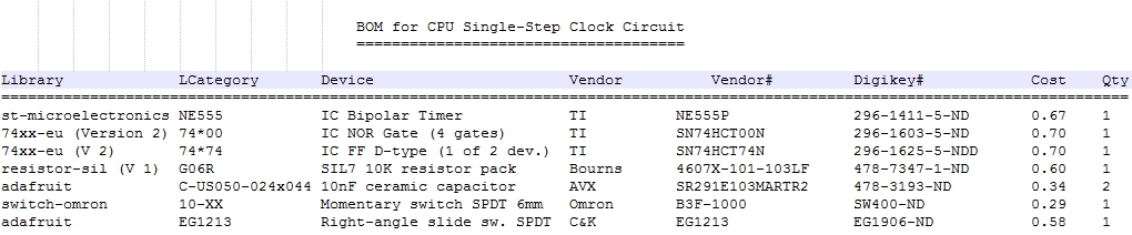
(Bill of Materials) |
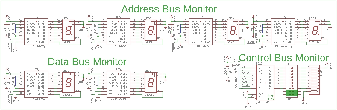
Eagle CAD: Z80 Bus Monitor
|
We could single-step the CPU with the CPU Single-Step Clock circuit using the bar graph LEDs above but it would be more interesting if we built a circuit containing 7-segment LEDs for the Address and Data Buses; bar graph LEDs will be used for the control signals. Do keep in mind that the MC14495 chip may no longer be in production which means the price may go up on eBay or wherever. You can always use a PAL to build your own. We'll use the adjacent Z80 Bus Monitor circuit to view the code and signals as we step through the program.
Test Your Circuit Visit CPU Single-Step Clock Test to test your circuit. |