|
CIRCUIT 1-6-3: 2x16 LCD using the 8255 PPI |
| Name | Circuit Schematics (click to enlarge) | Info |
|
I/O: 8255 OUTPUT with LCD panel
(Bill of Materials)
|
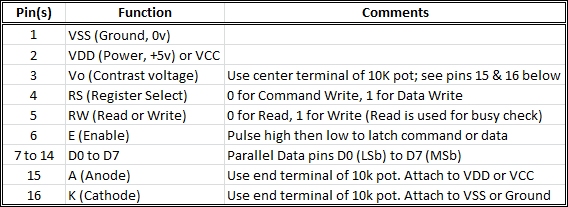
Eagle CAD: 8255, 2x16 LCD 16x2 LCD Pinout
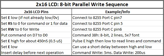
LCD Write Operation
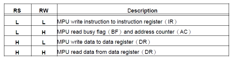
LCD Configuration: Bit Definition Modes
|
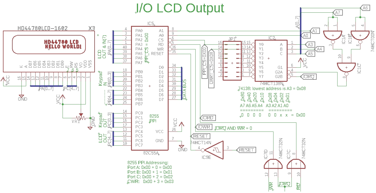
In this circuit, we replaced the '574 and LED bar graph with a
16x2
(16 columns by 2 rows)
parallel LCD panel.
The 1602-type LCD panel can use 4-bit or 8-bit data lines; 4-bit means multiplexing the 4 data lines which makes the coding a little more complex. We have all 8 data lines available on 8255 port A so we'll use them for 8-bit mode. Adjacent is a schematic for the circuit that includes the LCD panel. The adjacent LCD Write Operation chart shows the order of operation to output characters to the LCD. Essentially, it indicates the 3 control lines from the 8255 must be asserted before a control or data byte from the 8255 is sent to the LCD. To have the control lines and byte read/latched by the LCD, the LCD Enable line is pulsed high then low. We used Port B and Port C (low) for the keypad, so we have Port A and Port C (high) remaining for the LCD. Here's a summary of how we set up the keypad: - Port B output (Keypad OUT in the schematic) sends four binary combinations (00,01,10,11) to sequentially enable 4 keypad column lines. - Port C (low) input (Keypad IN in the schematic) reads the four column rows to detect a key press when the circuit is made through the pull-down resistors. - If the key press occurs while outputting to column 1, the row read gives us the column/row vector, e.g., column 1 row 2 yields the vector C1R2 which was being sent to the LED bar graph for display. In the next circuit we build, we'll send the key press vector to the LCD for display.
In this circuit we'll use Port C (high) for the control lines to the LCD and Port A to send display commands or display data to the LCD. The adjacent schematic shows the Port C (high) lines as PC[4..7]; we don't need pin 4, just 5 through 7.
Test Your Circuit Visit Z80 IO Output Test III to test your circuit. It contains useful info and a video demo. |