|
Input/Output Test III |
|
Output to LCD Panel using an 8255 PPI |
Resources |
|
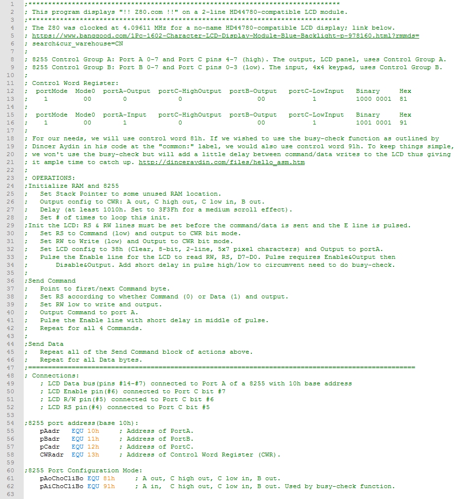
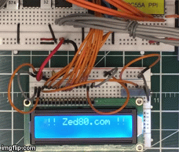
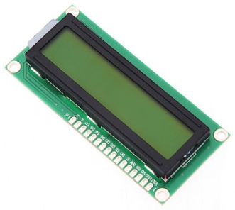
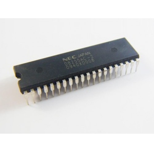
Overview: - In this test, we're going to wire a 2x16 Character LCD module to our 8255 PPI to display a line of text. - The LCD has 3 input control lines and 8 data lines. The data lines can be multiplexed down to 4 data lines if you're pin-limited but we won't be doing that. - We'll use 8255 Port A as an output for the Z80's data bus pins D0 to D7 on the LCD. - Port C on the 8255 can be split into Port C low (pins 0 to 3) and Port C high (pins 4 to 7). We'll use Port C high as output to set the control lines so we can write data to Port A. - We have already used Port C low and Port B for the keypad. We'll combine the LCD configuration with the keypad configuration of the 8255 in the next module, Input/Output Test IV.
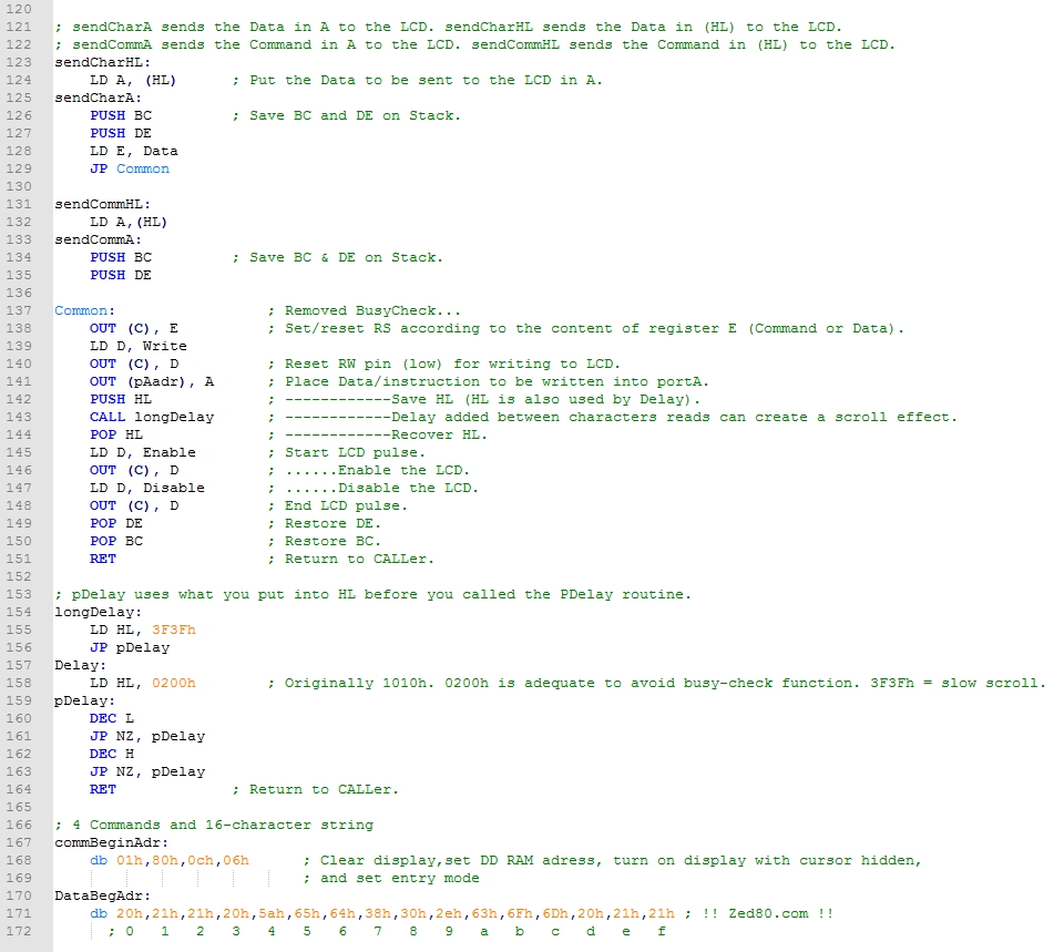
How does the circuit work? - There are there are 3 control pins, RS, R/W and E on the LCD in addition to the 8 data pins. One of the data pins, D7, can be used by the 8255 to poll the LCD panel to see if it's busy; we won't be using that function. - R/W is set to Write mode (0) as data is always sent from the microcontroller (MCU) to the LCD module and not in the opposite direction. The Read mode (1) is used to determine if the LCD is busy; we won't be using that function. - RS is the Register Select pin. It allows the LCD module to decide if data coming from the MCU must be interpreted as an LCD command (RS low) , or if it must be treated as text data (RS high) to be displayed on the LCD screen. - E enables LCD access for each MCU-to-LCD transaction. As soon as a communication starts from the MCU side, this pin must be set high to enable the LCD. On some LCD display controllers, you need to pulse this line low after pulsing it high. On others, it returns to low level once the procedure is completed. We're going to pulse it high, delay a moment and then pulse it low for the most common LCD panels/controllers.
Summary of Operation In summary, we set R/W low to Write, RS low for a Command or high for Data, send the Command or Data on D0-D7, and pulse E high then low to read/latch the 2 control lines and 8 data lines. To avoid the complexity of using the busy-check function, we'll add a little delay during the Enable pulse.
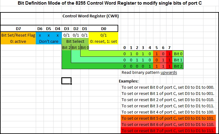
Examine the assembly code below for I/O Output Test III: - The code below is heavily documented to help you understand how the LCD is used by the 8255. - Zed80dotCom05-NoBusyDetect.asm is shown as 3 separate screenshots. - In Code - Part 2 below, assembly code lines 64 to 72 contain specific codes for setting the RS, R/W, and E lines for commands or data. The code values come from the adjacent diagram, 8255 Control Word to Modify Port C Bits. - The 8255 sets the control lines via the code values, a command or data is queued, and then the E line is Enabled and Disabled - that is, it's pulsed; this allows the lines and queue to be read.
Code - Part I Code - Part 2 Code - Part 3
How do I get this program onto my EEPROM? - The Zed80dotCom05-NoBusyDetect.zip file contains the .asm file, a .lst file showing the machine code and assembly language, an .obj file that contains just the machine code, and a .hex file. The hex file is in Intel format which is used by most "burners". - Up until now we have been limping along using a file I built for you so you could load it into your Arduino-based EEPROM burner. The files are now getting much bigger and taking too long build manually. It's time to consider buying a real EEPROM burner. Here's one that I have been using since June 7, 2018. It's easy to configure, easy to setup, easy to use each time, and is very reliable: it's a TL866 II Plus. Don't get the plain TL866 if you can afford the TL866 II Plus. I bought mine on eBay for $54.14us with free shipping, and it took 2 weeks to arrive from Shanghai CN. |
LCD/8255 Schematic
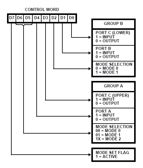
8255 Control Word Register (CWR) to Setup Ports
8255 Control Word to Modify Port C Bits
Video: 2x16 LCD panel output
Clicking the thumbnail gif above will provide an HD video (1.6MB, .mp4 format)
|

