|
Input/Output Test I |
| I/O Output Test Using an 82C55A PPI or Equivalent | Videos |
|
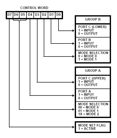
Reading and Writing to a PPI: - Reading from a device, Mode 0 for basic input - Writing to a device, Mode 0 for basic output
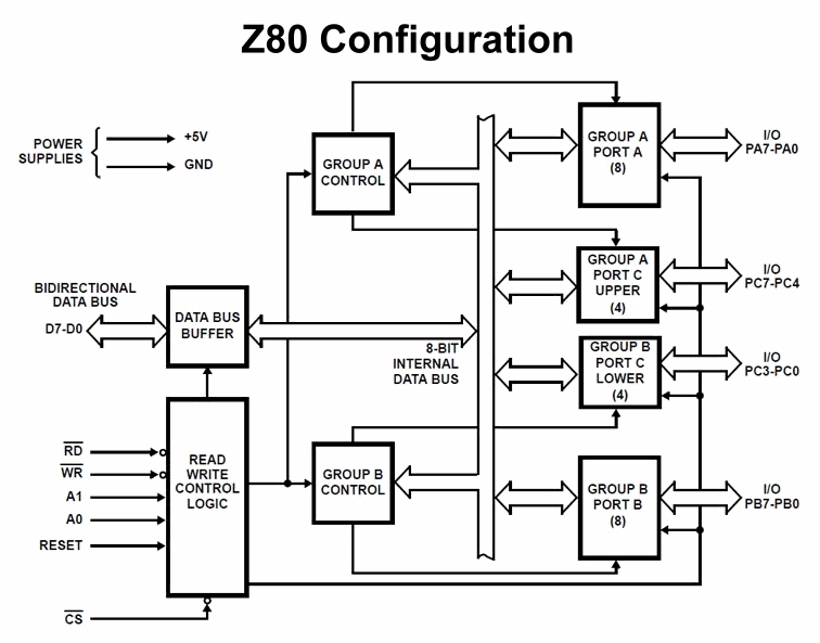
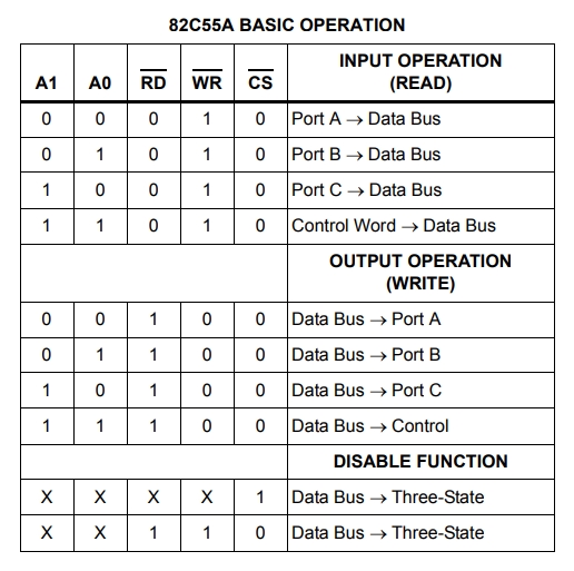
Reading from a device, Mode 0 for basic input: - CS0, A0 and A1 on 8255 are asserted - CPU Address Bus is set to the address of the device (0x00 to 0xFF) from which you're going to read. Only the lower 8 bits, A0-A7, are used for I/O - IORQ and RD are asserted low - The device will put the data on the Data Bus (D0-D7) for the CPU - The Z80 CPU will process the data and de-assert IORQ and RD
Writing to a device, Mode 0 for basic output: - CS0, A0 and A1 on 8255 are asserted - CPU Address Bus is set to the address of the device (0x00 to 0xFF) to which you're going to write. Only the lower 8 bits, A0-A7) are used for I/O - IORQ and WR are asserted low - The CPU will put the data on the Data Bus (D0-D7) for the device - The device will process the data and the CPU will de-assert IORQ and WR
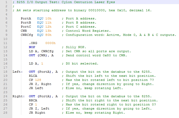
Examine the assembly code below for the I/O Output test: - 8255_Centurion.asm is documented below:
The Z80's Register A is used to set the 8255's Control Word Register so all ports are outputs in Mode 0 (Basic I/O mode). Then Register A is loaded with 1: this will fill the right-most bit of an 8-bit byte. In routine Left, the binary 1 is sent to the 8255's Port A using the OUT (PortA) command; it uses the EQU equate at the beginning of the assembly program to map PortA to address 0x10. Next, the A register is rotated left using RLCA. This moves the 1 in the ones-bit position to the twos-bit position. The value is compared to 128 which is the left-most position of an 8-bit byte. If the value is 0 because the value remainder was 0 when subtracted from 128, then we would jump to routine Right. The value is only 2 so we fall through this test and execution starts again at Left. Each time we pass thru the Left routine, the current value of the A register is output to the 8255's Port A. This has the effect of only lighting up the bit value of the current LED. In the next pass through the value is 4, then 8, 16, 32, 64, and finally 128. When this occurs, 128 subtract 128 is zero so we jump to routine Right. Each time we pass through the Right routine, the current value of the A register is output to the 8255's Port A. Again, this has the effect of only lighting up the bit value of the current LED. The Right routine is essentially the same as routine Left, except the comparison value is 1 which occupies the right-most bit position of a byte. The other difference with Right is this time the A register is rotated right using RRCA. The first value will be 128, then 64, 32, 16, 8, 4, 2, and finally 1 which will cause the routine to jump to Left. There is no exit from this program. The Left routine runs until the left-most bit is realized, then the right routine until the right-most bit is realized, ad infinitum. The net effect is the Cylon Centurion laser eyes display.
How do I get this program onto my EEPROM? Use the Z80_eprom_programmer.ino file. It contains everything you need in line 62 that begins with "byte data[]". Line 61 shows comment characters, //, indicating this line of code is for the Centurion program. You can see the other programs above these two lines commented out as well. |
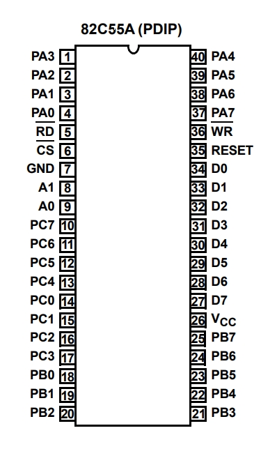
82C55A PPI, General Purpose Programmable I/O Device
Video 1: Z80 system executing an I/O output test
Clicking the thumbnail gif above will provide an HD video (1.7MB, .mp4 format)
Video 2: Similar to the one above but zoomed into just the I/O Output circuit
Clicking the thumbnail gif above will provide an HD video (3.8MB, .mp4 format) |