|
Build Your Own Z80: CIRCUIT 1-6-5 |
| Name | Circuit Schematics (click to enlarge) | Info |
|
IO: 8255 I/O with 4x4 Keypad and LCD Panel
(Bill of Materials)
|
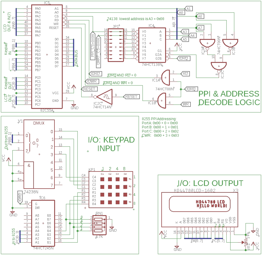
Eagle CAD: 8255, 4x4 Keypad, 2x16 LCD
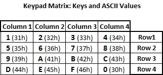
4x4 Keypad: Keys Matrix
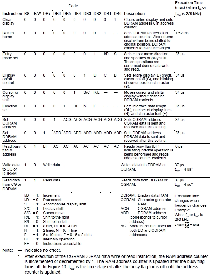
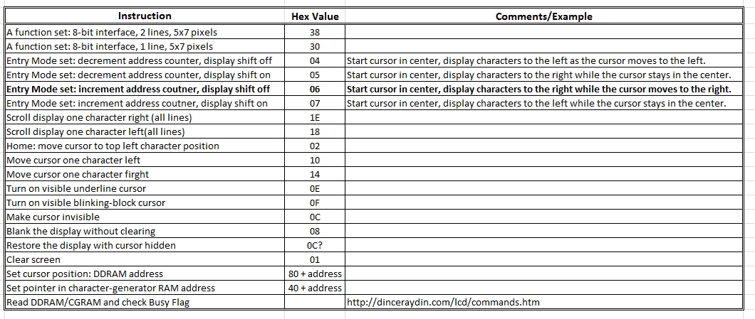
LCD Instruction Codes
|
The three previous I/O circuits and tests have led up to this one - input and output with an 8255 PPI. In this circuit, the keypad input and LCD output are merged together as assembler program Keypad-LCD-09_PPI-Address-00h_4.asm. Any key pressed will be displayed on the LCD panel in the left-most column.
Please note that we have changed the 74138 addressing wiring. You'll see it reflected in the adjacent schematic. This was necessary to make the addressing consistent for all I/O devices that would share the same 74138 3-line to 8-line decoder; alternatively we would have to add another '138 for each new device which would be a waste of printed circuit board space. (The 3 NAND gates in the upper right emulate an OR gate to ensure A3 through A7 are low to enable the 8255 PPI with I/O address 0x00. We could of used an OR gate but that would have meant more PCB real estate loss; we had spare NAND gates so...)
The first 93 lines of the .asm file are mostly documentation indicating how the two devices are configured and used with the 8255 PPI. Lines 70 to 76 show the keypad keys matrix.
The adjacent Keys Matrix chart displays the ASCII codes each of the 16 keys (0 to 9, A to F) will send to the LCD for display.
The software uses a polling method - not an interrupt method - to read the key presses. That means pressing any key for more than a fraction of a second will cause multiple sequential displays of the same key - not quite what we want. The apparent fix is to send the LCD command 02h after any key press which "homes" the LCD cursor, effectively "erasing" the multiple displays of the same character.
When configuring the 8255, note that we will be using port C low and port C high in addition to ports A and B. Port C low is the only input port.
There are several commands listed in the adjacent LCD Instruction Codes chart as well as a simpler version found on the Test page as LCD Instructions. You may wish to experiment with them.
Test Your Circuit Visit Z80 IO Output Test IV to test your circuit. It contains useful info and a video demo.
|