|
CIRCUIT 1-7-2: Programming the CTC Channels |
| Resources (click to enlarge) | Info |
|
1. Port Addresses
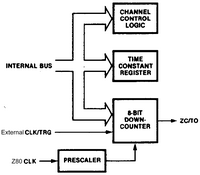
2. Counter/Timer Block Diagram
4. Channel Control Word Clarification
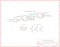
5. Eagle Schematic: CTC & Addressing Logic
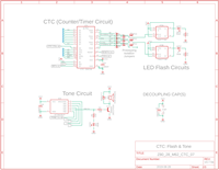
6. Eagle Schematic: LEDs & Tone Flasher
|
Programming Bytes The CTC allows relatively easy programming: each channel is programmed with one or two bytes; a third is necessary when Interrupts are enabled. When started, a CTC channel counts down to zero, automatically reloads its time constant and resumes counting.
Operation During operation the individual counter channels count down from their preset Time Constant value. In Counter Mode operation the counter decrements on each of the CLK/TRG (Clock/Trigger) input pulses until zero count is reached. The decrements are synchronized by the Z80 CPU system clock. For counts greater than 256, more than one counter can be cascaded. As an example, CH0 output could be connected to CH1 input. Time intervals are generated by dividing the system clock with a Prescaler that can decrement a preset down-counter. The Prescaler can be 16 or 256. Using an input channel in Timer mode, if we take a 4MHz CPU clock, use a max Prescaler of 256 and a max Time Constant of 256, then the output pulse from TOx will be 4,000,000Hz / 256 Prescaler / 256 Time Constant, for a result of 61Hz. If we feed that channel's output into another channel's input in Counter Mode (no Prescaler) with a counter set to 61, then we would get its output pulse approximately every 1 second.
Z80-to-CTC Address Lines We used the first 74138 as well as Address Bus address lines A0 and A1 to assign addresses $30-$33 to the four channels, CH0 to CH3, and $34 to TONE_1. At the top of the adjacent Resources panel you can see the code used to equate the port names with the assigned addresses. An I/O read (IN command) can be used at any time to determine the remaining count assigned to a CTC channel as it counts down.
What do we need to know about the CTC functions? Time Constant Register: - Stores an 8-bit constant value of your choosing between 1 and 256 - It's automatically loaded into the down-counter when the channel is initialized, and after each zero count Prescaler: - Only used in Timer Mode not Counter Mode - Divides the system clock frequency by either 16 or 256 - Prescaler output clocks the down-counter during Timer Mode operation Down-Counter: - Loaded with the Time Constant Register contents (1 to 256) prior to each count cycle - Decremented by the system CPU clock Prescaler output in Timer Mode - Decremented by the external trigger pulses into the CLK/TRG input in Counter Mode - Any of the four CTC channels can be programmed to generate an Interrupt request to the CPU each time the zero count is reached
Confused? If differentiating Timer mode from Counter mode gets confusing, try to remember that a clock is essentially a timer: Timer Mode uses the system CPU Clock which you'll usually provide from the Z80 CPU's CLK signal. Check out the second diagram from the top in the Resources panel to see how the Z80 CLK (CTC CLK) is connected to the Prescaler. So think of Timer Mode as internal clock, and Counter mode as external clock or pulses.
INs and OUTs Each CTC channel is composed of an input (CLK/TRGx) and an output (ZC/TOx). (Note that channel 3 (CH3) does not have an output.) The output of one channel, e.g., CH0, can be connected to the input of another channel, e.g., CH1. In Counter mode, every active edge on the input pin(s) decrements the down counter. In Timer mode, an active edge starts the timer.
Using both Timer and Counter Our design will include both the Timer Mode and Counter Mode functions. In Timer Mode, we're going to get Channel 0 to use the Prescaler to divide the 4MHz CPU Clock by 256; the result will be 15,625Hz. Then we'll use a Time Constant of 256 to further divide the system clock down to 61.035Hz for the same channel. So each time the Prescaler ticks down the system Clock by 256, the Time Constant is ticked down 1. The output of channel 0 (we'll call it CH0) will go to the flip-flop attached to LED1 so we should see it flash 61 times per second, but the F-F halves the input so the flash rate will be about 30 flashes per second which we can distinguish visually from a solid signal. Next in our flasher design we can feed the CH0 output signal of 61.035Hz to the input of Channel 1 in Counter Mode. Using a Time Constant of 61, we can get it to trigger every 61.035Hz / 61 second or very close to one second. This we'll use to flash LED2 via another F-F. With the input rate halved, we expect it to flash every 2 seconds. But wait, we're not done yet. If we feed the 1Hz signal output of Channel 1 to the input of Channel 2 in Counter Mode and use a Time Constant of 10, we can get it to trigger every 10 seconds. That is the purpose of LED3 in the adjacent schematic. You could, of course, change the counter to anything you like.
How does the circuit work exactly? Check out the adjacent lower schematic to see the actual CTC connections. Channel 0: - Set the Control word to indicate Timer mode, Prescaler of 256, Time Constant of 256. Result is 61.035Hz - Connect Channel 0 output to Channel 1 input and to LED1. The 7474 flip-flop will halve the flash rate to 30 which is distinguishable from a steady light. Channel 1: - Set the Control word to indicate Counter mode and Time Constant of 61. Result is 1Hz. - Connect Channel 1 output to Channel 2 input and to 1 Second Heartbeat LED (LED2) Channel 2: - Set the Control word to indicate Counter mode and Time Constant of 10. Result is 0.1Hz (every 10 seconds) - Connect Channel 2 output to Channel 3 input and to 10 Second Heartbeat LED (LED3) Channel 3: - Set the Control word to indicate Timer mode, no Time Constant follows. This effectively disables the channel. L - Later we'll enable the channel to use it for interrupts.
The CTC_3ch_0int.asm program containing the .asm source code, .lst listing file, and .bin binary can be found in the link at the bottom of the adjacent panel.
How do I use the file? Run CTC_3ch_0int.asm as a standalone program at location $4000. If you add interrupts, you may need to modify the EEPROM to accommodate an Interrupt Vector Service Routine (ISR). Alternatively, you could specify Interrupt Mode 2 and just put the ISR at the end of your program: a lot more convenient than having to reassemble your ROM Monitor or ROM BIOS to accommodate the interrupt routine. We'll look at Interrupts next. |
| NEXT PAGE: CTC Interrupts => | |
Tags: Z80 CTC, Z84C30


