|
CIRCUIT 1-7-3: CTC Interrupts |
|
Resources (click to enlarge) |
Info |
|
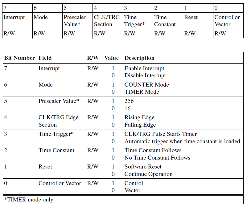
1a. Channel Control Register/Word
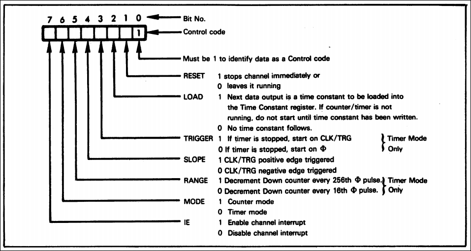
1b. Channel Control Word Clarification
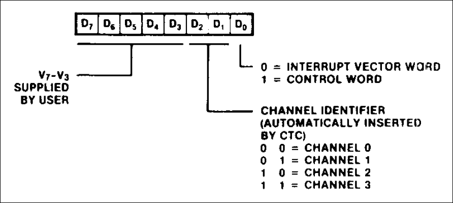
2a. Interrupt Vector Word that becomes IVR
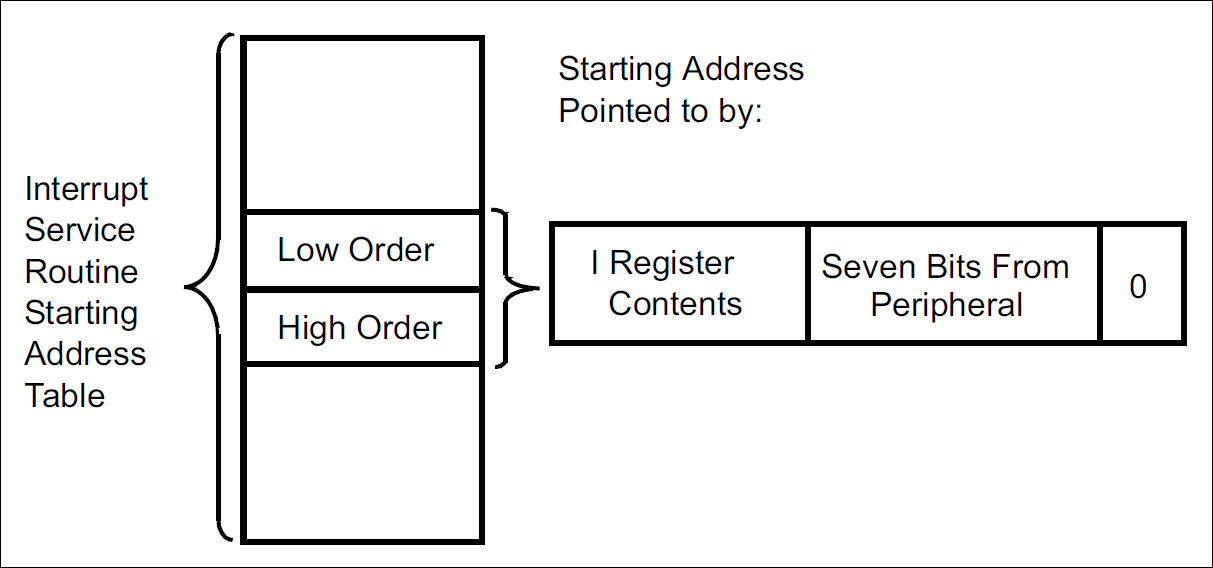
2b. IST from IVR
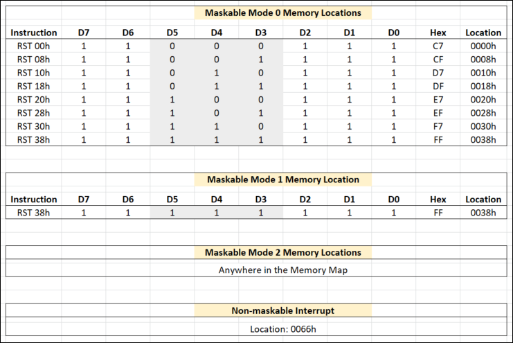
3. Interrupt Modes & Addresses
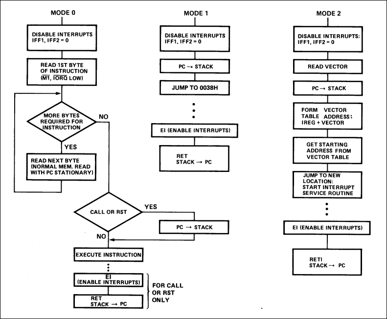
4. Maskable Interrupt Sequences: IM0, IM1, IM2
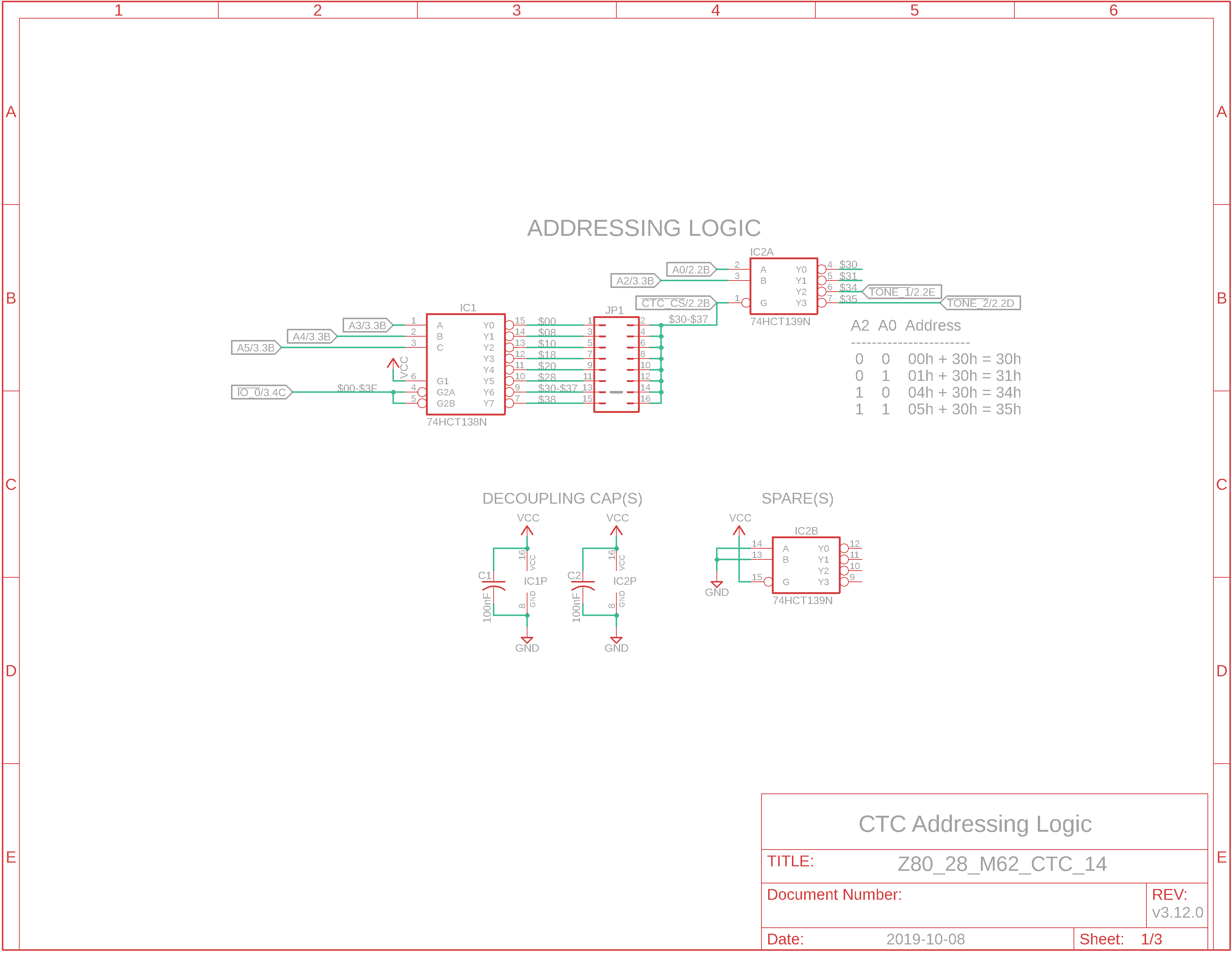
5. Eagle Schematic: Addressing Logic
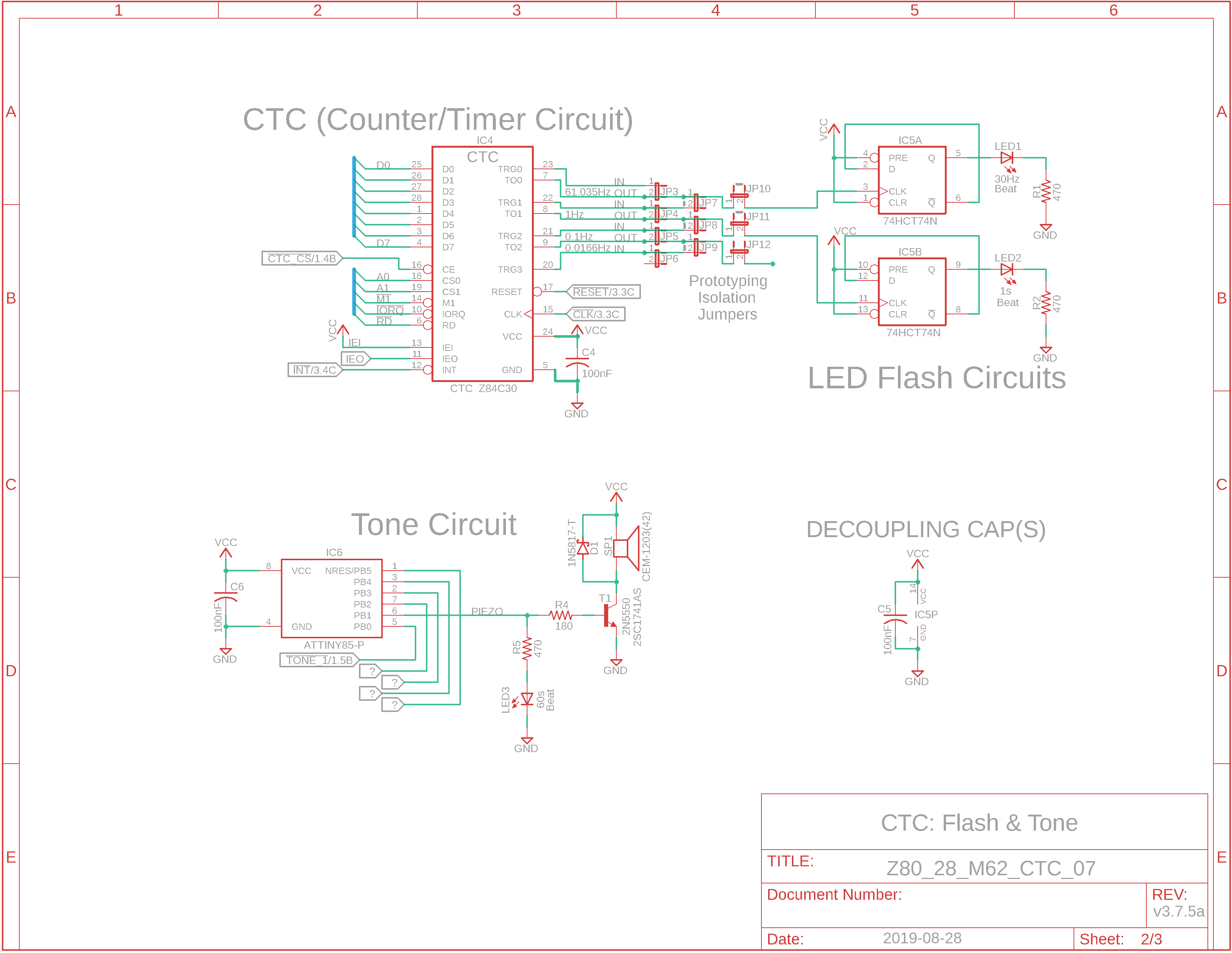
6. Eagle Schematic: LEDs & Tone Flasher
7. INT Trigger and IVR
8. Source Code: CTC_4ch_1int.asm
|
Interrupts The purpose of an interrupt is to interrupt the normal Z80 CPU workflow to execute an interrupt service routine.
Good reference docs for Z80 Interrupts: - The Z80 CPU User Manual introduces Interrupts (page 17) - In the Z80 Family CPU Peripherals doc (page 22) their CTC configuration is more complete . You could also search for "Interrupts" or "Vector". - Chapter 12 (page 293) of The Z80 Microprocessor - Chapter 16 of Practical Microcomputer Programming. - The Z80 Family Program Interrupt Structure
Interrupt Modes There are two types of Interrupts - maskable and non-maskable (NMI, address 0066h, cannot be disabled, and requires immediate CPU response). The Z80 uses 3 modes of operation for maskable interrupts. There is also a non-maskable interrupt known as NMI. Many implementations choose maskable interrupt Mode 1 with the Assembly Language instruction RST 0038h; the service routine (or a pointer to it) will need to be located at this address. Usually it will be a jump to a different location for the entire interrupt service routine. The panel-adjacent table, 3. Interrupt Modes & Addresses, differentiates the four modes. CTC channel interrupts can be programmed in either Counter or Timer mode; we'll use Counter mode.
Interrupt Priority The CTC uses Interrupt Control Logic to ensure it works properly with the Z80's nested priority interrupting and return system. The position of the device in the daisy-chain determines its priority: the device closest to the Z80 has highest priority. Within the CTC device, Channel 0 has the highest interrupt priority and Channel 3 has the lowest. The Z80 CPU Peripherals document discusses Daisy-Chain Interrupt Servicing on page 30. We won't use interrupt daisy-chaining with only one interrupting device, the CTC.
Interrupt Instructions and Modes (Maskable Interrupts - not NMI) At the beginning of your code, you can enable interrupts with the one-byte instruction, EI (enable interrupt). You may want to remove "DI", disable interrupts, from your BIOS code if you want to ensure interrupts fire. EI should also be used at the end of your Interrupt Service Routine (ISR) because the interrupt process is automatically disabled during the ISR to permit the daisy-chain interrupt logic to complete, and also to prevent conflicts. Set the interrupt mode using instructions IM 0, IM 1, or IM 2 (interrupt mode 2). The CTC requires Interrupt Mode 2 although I have made it work with Interrupt Mode 1. RETI is specially designed to reset the Z80 daisy-chain interrupt logic, and is used as a return from interrupt. Place this at the end of your ISR.
Interrupt Modes: Mode 0: program execution can be transferred to one of the eight memory locations shown in the adjacent 3. Interrupt Modes & Addresses table. Mode 1: program execution is transferred to location 0038h; no extra hardware needed. This will prob'ly be the FlashROM in your system. Mode 2: this mode supports putting your ISR anywhere in memory. The 2-byte Interrupt Vector Register, I, contains a portion of the 16-bit address that program execution is to be transferred to. The IV Register contains the top 8 bits and you need to provide the lower 8 bits either through external hardware or via the 2a. Interrupt Vector Word (IVW) to create the full 16-bit Mode 2 address. If we want a CTC channel to request an interrupt every time its down-counter reaches zero, we'll have to program the Z80 to use Interrupt Mode 2. Once the CPU receives the interrupt request (INT goes low briefly) from the CTC, it sends out an interrupt acknowledge (M1 and IORQ asserted low) to the CTC. If the CTC's IEI (Interrupt Enable In) line is active (H), then it has priority over other interrupting devices connected to the Z80. In our designs, we'll pull IEI high through a 10K pullup resistor. If you decide to add other interrupting devices to your design, there is a flying lead jumper for IEO(Interrupt Enable Out) in the CTC board section; IEO from the CTC would be connected to the IEI of the next interrupting device.
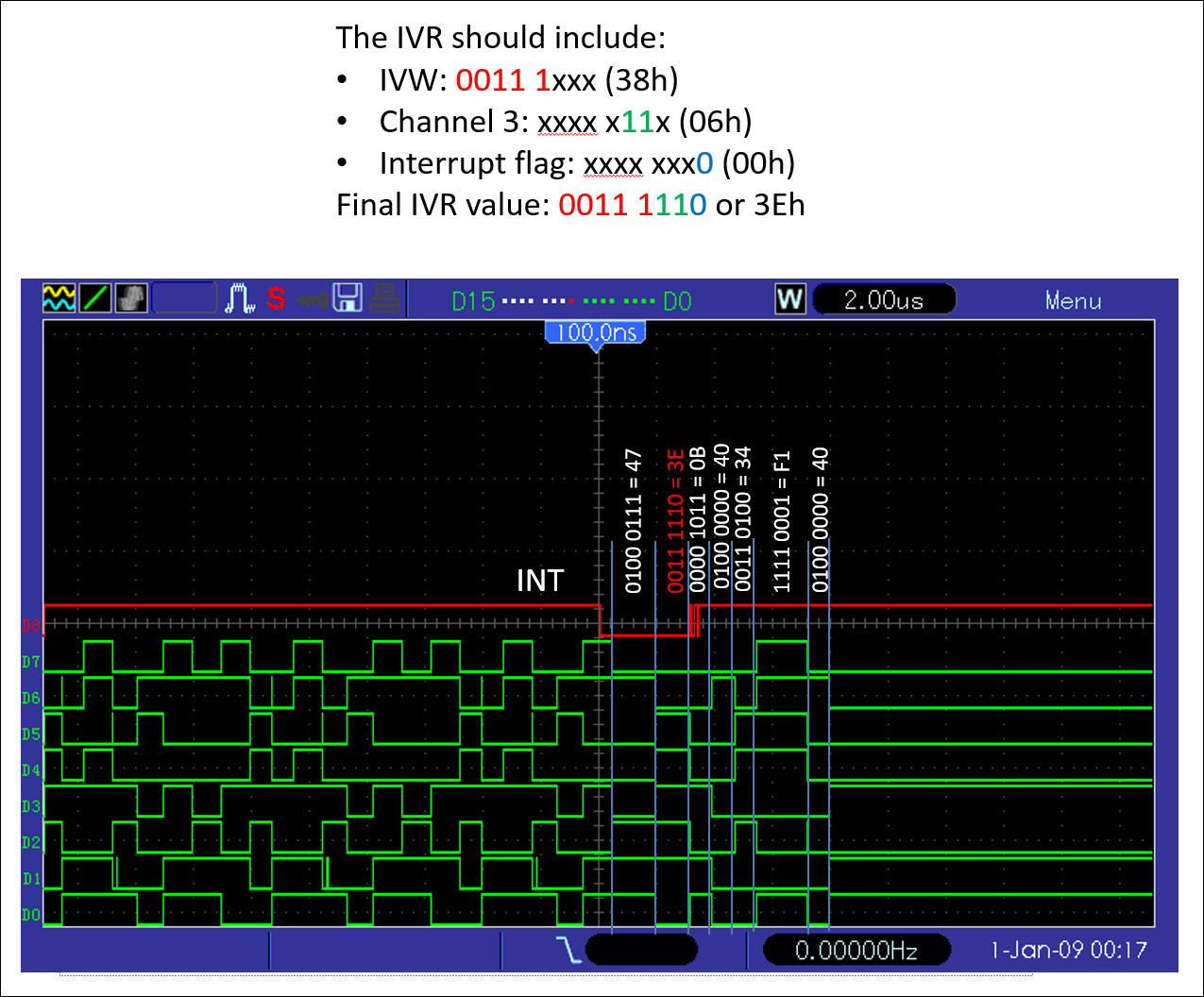
Interrupt Vector Word (IVW: from you to CTC) versus Interrupt Vector Register (IVR: CTC to CPU) An IVW is what you configure for the CTC so that it knows "this" channel will require an interrupt be sent to the CPU to service "this" channel. Bit 7 of the regular control word will be a 1 indicating an interrupt is needed. For the CPU to know the address of the interrupt service routine (ISR), it needs to be provided the upper 8 bits and lower 8 bits of the 16-bit address: - the "LD I, A" command provides the upper 8 bits to the Interrupt Register (IR). We would like to use interrupt service routine (ISR) address 4038h so we'll set A to 40h prior to executing this command. - when you configure the IVW, you indicate it's an IVW by setting bit 0 to 0 for Interrupt Vector and not 1 for Control Word. See the adjacent diagram, 2a. Interrupt Vector Word - bits 2 and 1 of the IVW are left at 00. When the CTC uses your IVW to create its own IVR to the CPU, it will replace those two bits with the channel number. In our example, that will be xxxx x11xb for CH3. This will be an index into the Interrupt Service Table. More on that later. In the adjacent panel you'll find a screenshot (7. INT Trigger and IVR) taken from my scope/logic analyzer that shows the interrupt firing and the IVR being placed on the data bus by the end of the INT pulse.
Interrupt Vector, Interrupt Service Routine (ISR) If the CTC has one or more interrupts enabled, it can supply interrupt vectors to the Z80. As discussed above, in Interrupt Mode 2 the CPU takes the eight bits from the interrupt register, I, as the high-order byte and combines it with an external byte (from the IVR in our case) as the low-order byte to form a 16-bit vector address. That means the interrupt service routine can be loaded anywhere in memory unlike Mode 0 or 1 where the vector should be in the first $0100 bytes which is typically ROM. The CTC has 4 channels. Each will require and Interrupt Service Table (IST) entry or vector as they are commonly known. Each vector is 2 bytes in length so we'll need 8 bytes for our IST. This means the low-order byte must end in either 0 or 8. Failure to do so will cause grief due to the way bits 2 and 1 of the IVR point to the IST vector's index. Our code is 37h bytes in length. The beginning of our RAM is 4000h and that's where we'll set our ".ORG" to run the program we write. If we use the first even address ending in 8 or 0 after the end of our code, then the ISR could be located at address 4038h. We can set an additional ".ORG" to ensure the ISR is at that address. In summary, there will be two ".ORG" statements: the first to run the app prob'ly at $4000, and the second for our interrupt service routine at $4038. The unused areas in between these groups of code can be filled with zeroes by using "tasm.exe -80 -x -g3 -c -f00 %f %n.bin"
Here's what our ISR will do: - save the existing registers and flags - output a 0 to I/O address 34h to trigger the baby Arduino (ATtiny85) to play a tune - after a short delay, output a 1 to cease that activity - restore the registers and flags - re-enable interrupts (using EI) that the system silently ceased in order to first process others in the daisy chain - return from interrupt (RETI)
Config Summary Let's review the configuration one more time for just channel 3. There will be three control words for channel 3. The first control word will have bit 7 set to a 1 to indicate an interrupt is needed and that an IVW will follow. When the IVW follows is dependent on bit 2 in the first control word. If bit 2 reads 1, then the next word (2nd word) will be the Time Constant word. The IVW will be after that word (it's the 3rd word). However, if bit 2 is a 0, then no Time Constant word follows so the 2nd word will be the IVW instead. In our example, bit 2 will read 1 so a Time Constant word will follow as the second word, and a third word (the IVW) will follow.
Here's our example in its entirety: - First word: Control word, bit 7 = 1 (interrupt needed) and bit 2 = 1 (Time Constant word follows) - Second word: Time Constant word (we'll use 4 to divide the CH2 signal by 4) - Third word: IVW, the lower 8 bits (the first 5 bits actually) of the ISR address (0011 1xxxb) 38h in our example), bits 2 and 1 = 0, bit 0 = 0 (interrupt vector)
What does the CTC do with the IVW? The CTC takes the Interrupt Register value of 40h you programmed earlier, combines it with the lower 8 bits of the IVW (address 38h in our example), changes bits 2 and 1 of the IVW to 11b to indicate channel 3, and sends the completed Interrupt Vector Register (IVR) to the CPU for processing. You will need a logic analyzer to see this. The CPU looks at the incoming IVR, knows it's an interrupt (bit 0 = 0), determines it's for channel 3 (bits 2 and 1 = 1), computes it's for address 4038h because it already added the IR value of 40h to the IVW value of 38h. Additionally, Interrupt Enable In (IEI) is high so it concludes this is the highest priority in the daisy chain and processes it as soon as possible. However, address 4038h is NOT the address of our ISR; it's the address of the interrupt service table (IST). Why? So that more than one interrupt can be configured for the CTC or other devices. IR: 4000h IVW: 0038h CH3: 06h (xxxx x11x) 4000h + 0038h + 06h = 403Eh. Examine 7. INT Trigger and IVR in the adjacent panel and you'll see the 3Eh component "decoded" from the data bus.
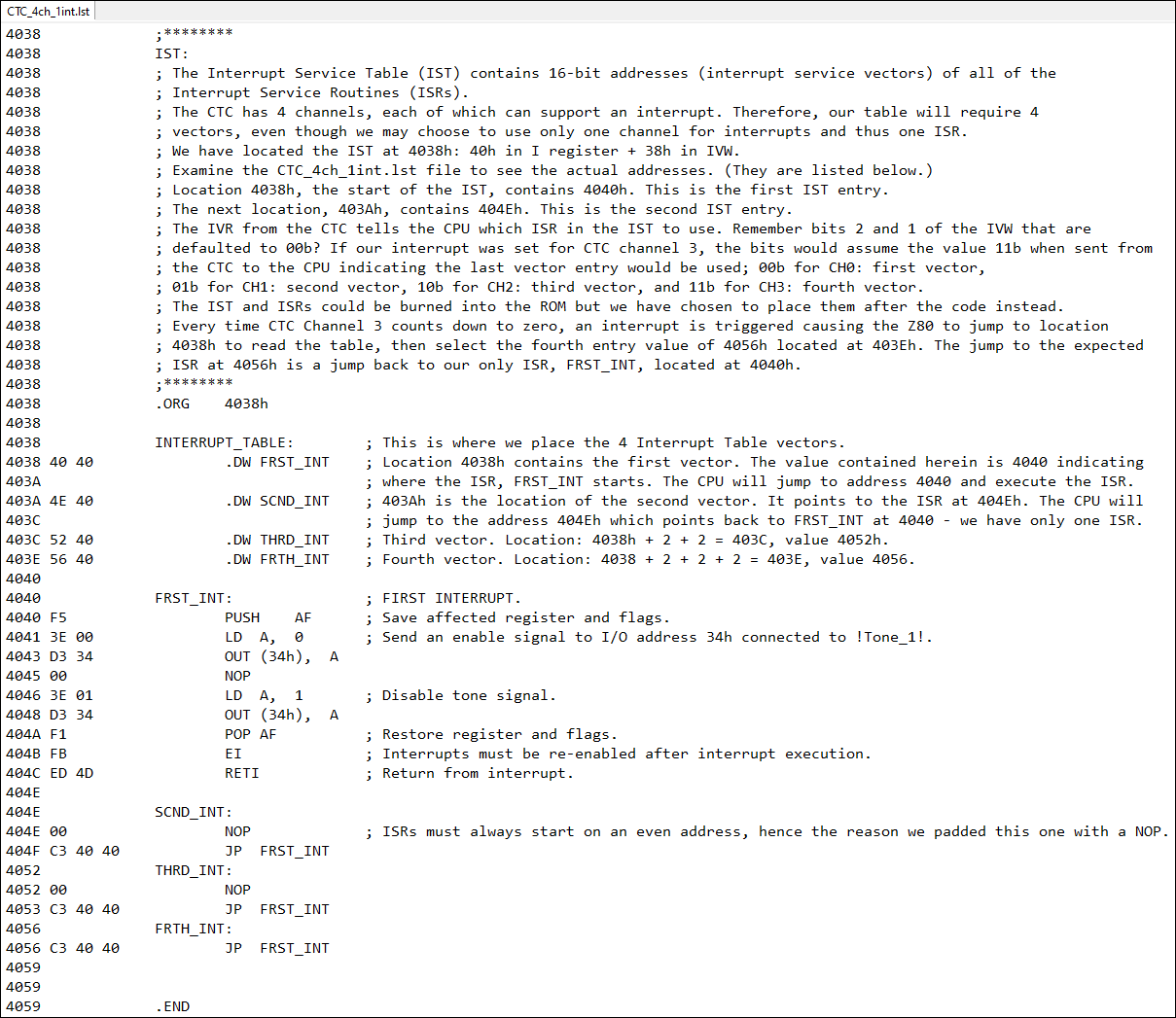
So exactly where is our ISR? Address 4038h is the start of a table of four ISR vectors. Even though we have only channel (CH3) that will use interrupts, the table must be populated as if there were 4 ISRs. With 4038h as the start of the IST, the first pointer to the first ISR will be at 4038h. The addresses/table entries each occupy 2 bytes so the pointer to the second ISR will be at 403A, the third at 403C and the fourth at 404E. Examine a screenshot of the .IST file produced by TASM v3.2.3 below. At 4038h, we have defined a word FRST_INT. This is the first entry in the IS Table. It indicates the IS Routine is located at 4040h. Remember to read the vector addresses in reverse as per the Z80 spec. When you navigate to 4040h, you can see we have used the label FRST_INT to indicate the start of the ISR which stipulates saving the AF registers, etc. The first IST vector is at 4038h and points to the ISR at 4040h. The second IST vector is 2 bytes later at 403Ah and points to the ISR at 404Eh which is labeled SCND_INT. If you navigate to that address, you'll notice the ISR points back to FRST_INT because we have only one real ISR. The third IST vector is at 403Ch and points to the ISR at 4052h, labeled THRD_INT. The fourth IST vector is at 403Eh and points to the ISR at 4056h, labeled FRTH_INT. Check out the adjacent diagram, 2b. IST from IVR if you need a visual representation of the IVR.
The code below contains the IST and four ISRs.
Daisy Chains With only one device (the CTC) in our Z80 system, we'll force the priority by tying IEI (pin 13) high to VCC. Pin 12, INT, goes to the CPU via the M62 bus. There are no other devices utilizing interrupts in our M62-bus system so we can just let the output IEO (Interrupt Enable Out) line on pin 11 float. IEO will be connected to the second device's IEI, and its IEO will be attached to the third device's IEI line, etc.
What does the Assembly code look like? The entire program is listed as the last item in the adjacent panel as CTC_4ch_1int.asm.
What if I want to use Interrupt Mode 1 (address 0038h) instead of IM2? As part of the initial testing when I had difficulty getting Interrupt Mode 2 to work reliably, I resorted to writing the code for Interrupt Mode 1 that uses the hardcoded address of 0038h. I put it on a FlashROM - no Monitor nor BIOS was used - just the raw program. I have included it here as well as the DSLogic logic analyzer (LA) screenshot and a short video showing the board working with the ROM code. In the LA screenshot, you can see the "3E" data immediately after the INT line goes high; this is the Interrupt Vector Register value going from CTC to CPU. The IVR breaks down as follows: IVR 00111 11 0b 00111 xx xb: address 38h xxxxx 11 xb: channel 3 xxxxx xx 0b: interrupt
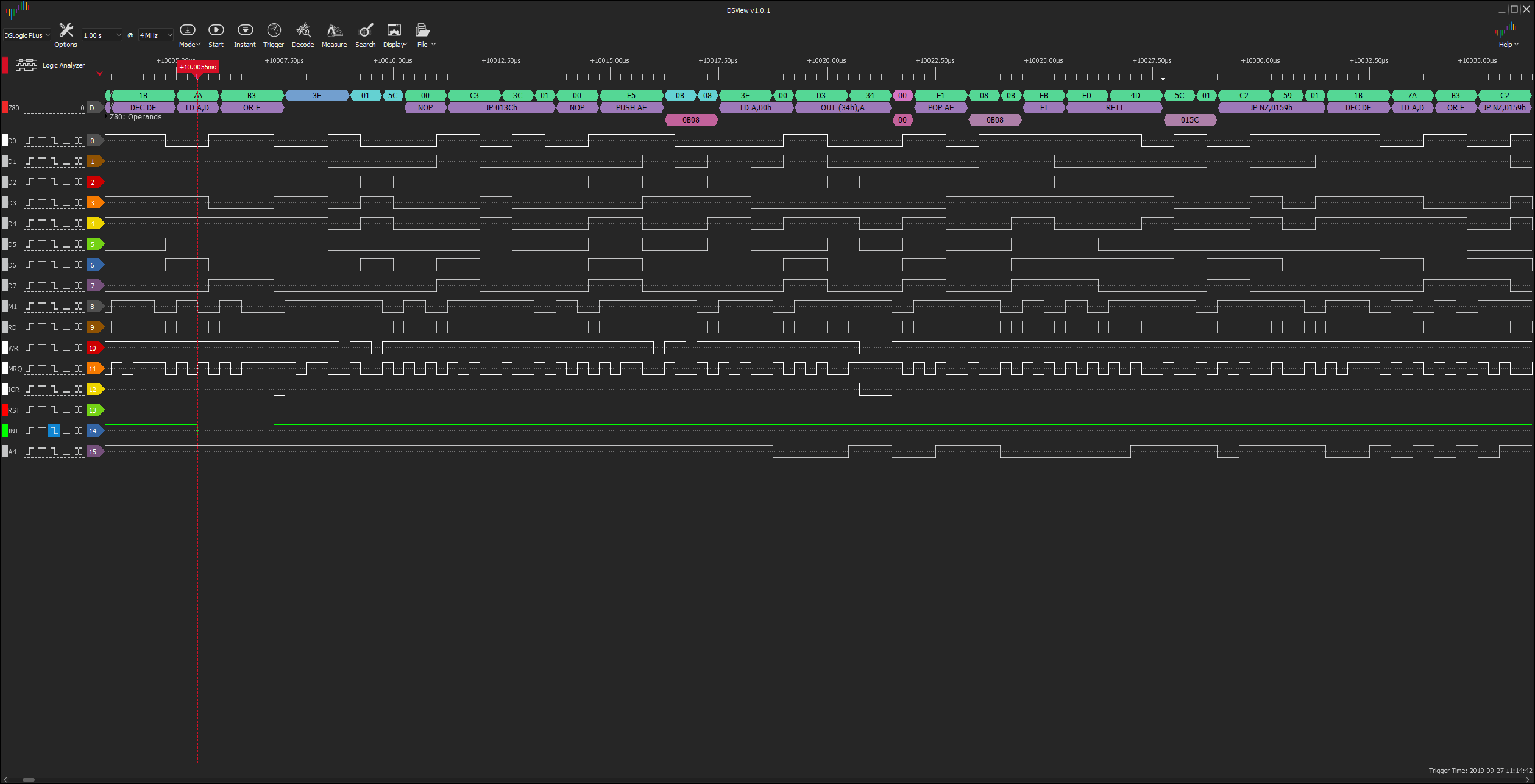
Now examine the Boot_CTC_IM1__03.lst file. At location 0038h you see: 00 NOP C3 3C 01 JP InitINT ; (JP 013Ch) This could have been the interrupt service routine at 0038h but instead it's a jump to the actual routine at location 013Ch.
Navigate to location 013Ch in the .lst file. It should read as follows: F3 DI 00 NOP F5 PUSH AF 3E 00 LD A, 0 D3 34 OUT (34h), A 00 NOP 3E 01 LD A, 1 D3 34 OUT (34h), A F1 POP AF FB EI ED 4D RETI
Now compare this with the code you see at the top of the LA screenshot, CTC_Boot_IM1__03.PNG: they should be similar. Note: they are not the same because I modified the ISR to not include "NOP", "LD A,1", and "OUT (34h),A". However, you can see the jump to 013Ch, the NOP, the PUSH AF, etc. (Further down on this page I use both "enable" and "disable" statements via 4 stretched screenshots.)
Once the ISR has completed, the remainder of the instruction "JP NZ, 0164h" that was being executed when INT went active low, is put back onto the stack so the instruction can complete. The rest of the Delay Routine continues to run.
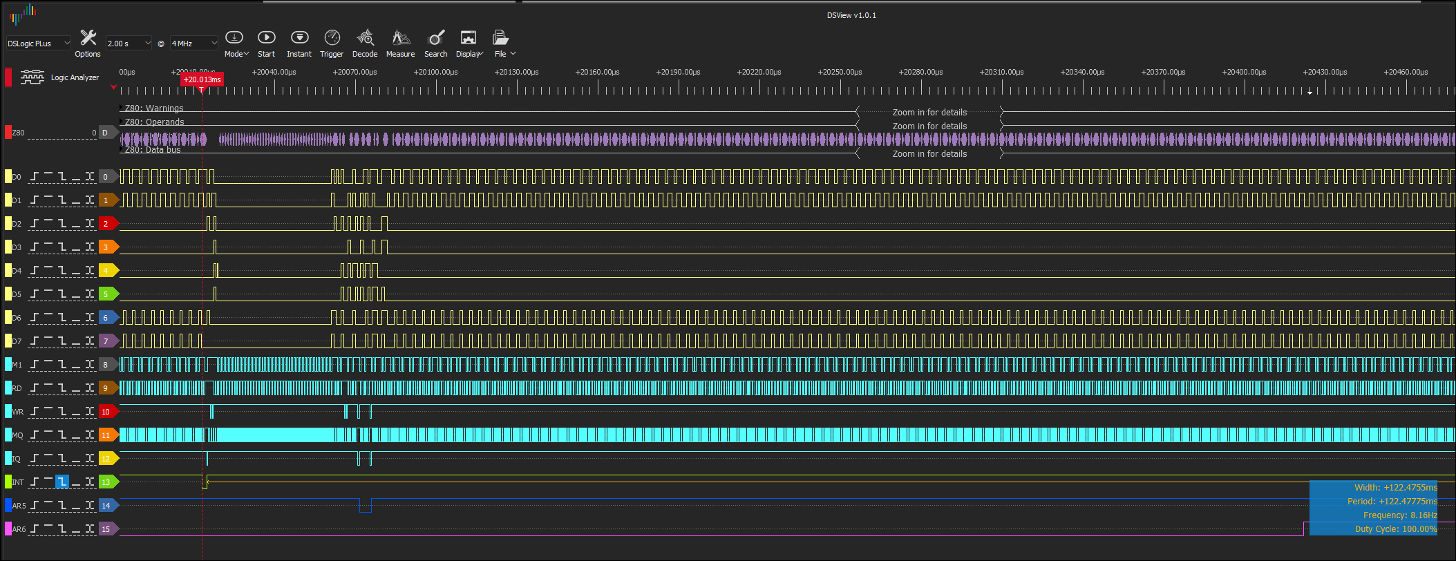
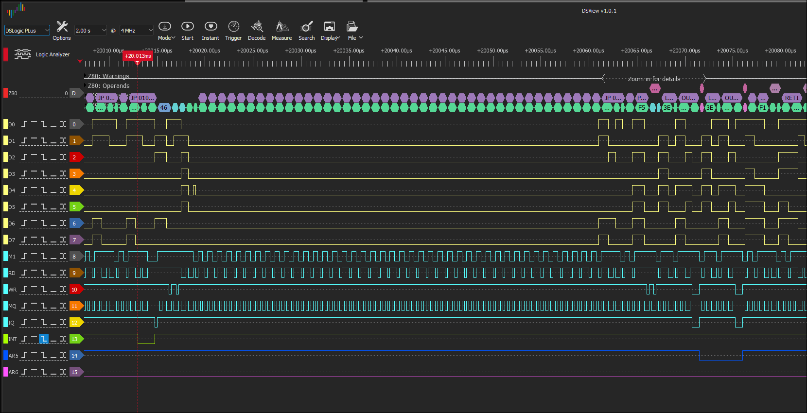
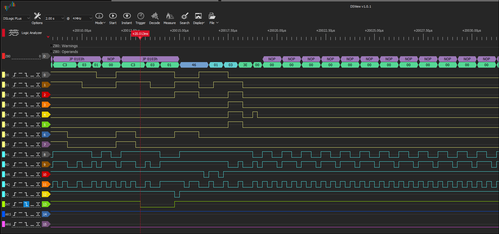
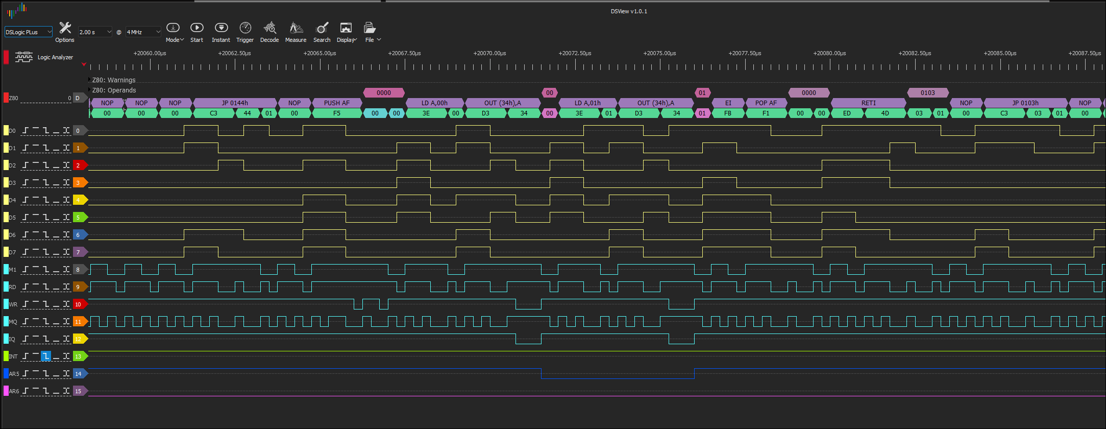
Interrupt Mode 2 on FlashROM Also available are the files needed to try Interrupt Mode 2 at location 0140h on FlashROM. Here are 4 file-embedded screenshots showing: 1) In the first Logic Analyzer screenshot below, the green INT line goes active low briefly as the CTC interrupts the CPU. The dark blue line AR5 is the input pin 5 of the ARduino ATtiny85. The signal is first output from pin 11 of IC3, the '138. This signal then travels through a 7474 latch to stretch its size by doubling it. From there it goes to pin 5 of the ATtiny85. In the Logic Analyzer screenshot we see it as a brief low signal before it returns to a high state. Also in this screenshot is the purple AR6 line which is normally low and then goes high much later as the ATtiny85 sends a tone/melody signal out pin 6 to the tone circuit. 2) In the second LA screenshot, we see INT go low briefly as well as Arduino pin 5 (AR5). Clearly, the AR5 signal is wider than INT due to the latch. Looking at the yellow data lines D0 to D7 further up in the diagram, there appears to be no data as the CPU sends out 00h NOPs while it prepares for the IM 2 interrupt. 3) In the third LA screenshot, we can see the IVR of 46h being sent followed by the NOPs of 00h. 4) In the fourth LA screenshot on the left, you can see the Interrupt Service Routine start after the NOPs end. It begins with JP 0144h, followed by NOP and PUSH AF. The ISR continues until we finally see the return from interrupt RETI.
1)
If IM 1 works so well, why don't we use it for everything? Because it only supports one ISR address so we could not use it for other devices. Could we use IM 0 that supports several addresses, starting at 0, that are multiples of 08h? My research and experimentation suggest the answer is No. Additionally, Zilog's CTC docs indicate IM 2 is needed (even though we got IM 1 to work). |
| NEXT PAGE: Programming the Arduino Tone Generator => | |
![]()
Tags: Z80 CTC, Z84C30, Interrupts, Logic Analyzer