|
CIRCUIT 1-7-4: Programming the Arduino Tone Generator |
| Resources (click to enlarge) | Info |
|
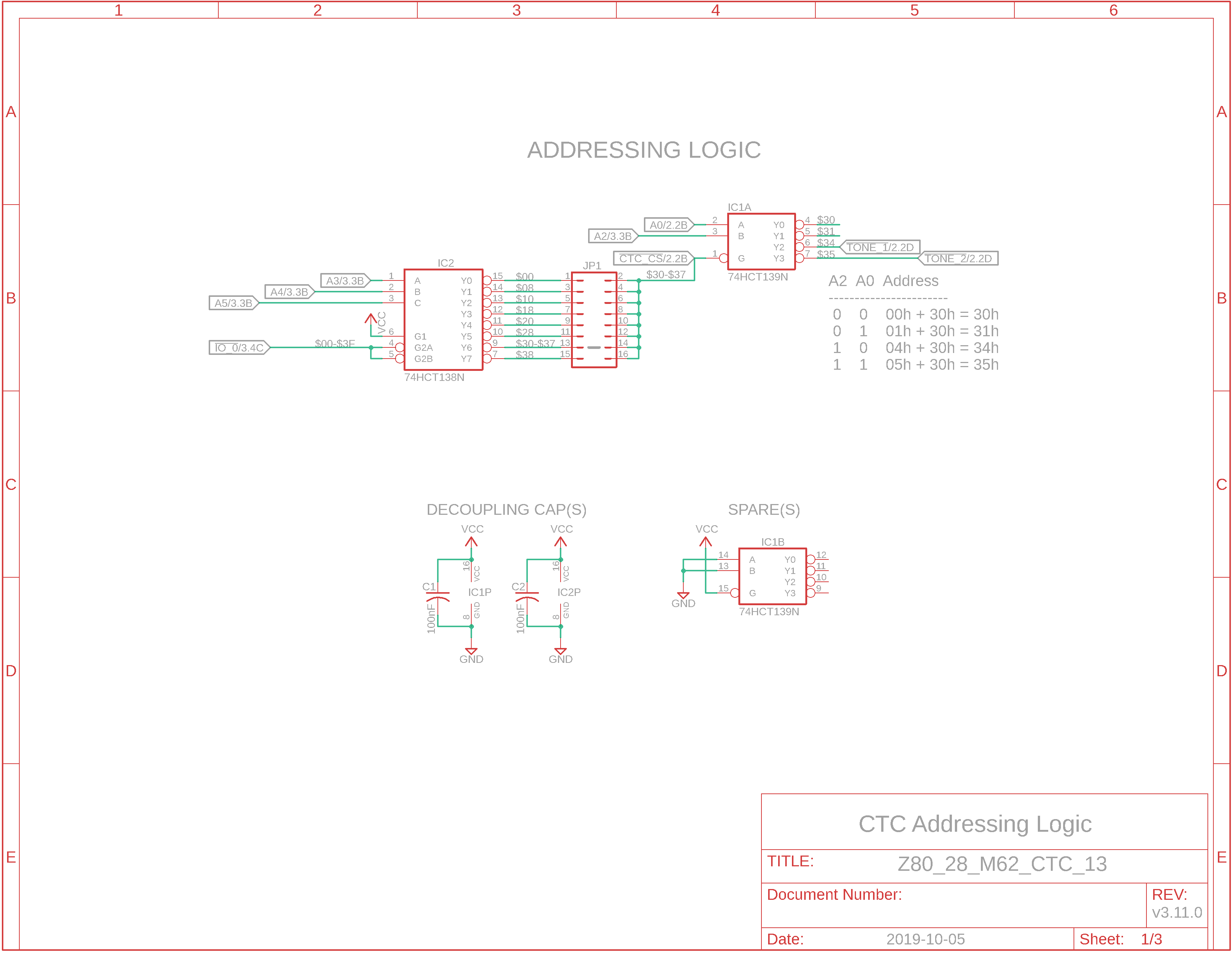
Eagle Schematic: Addressing Logic
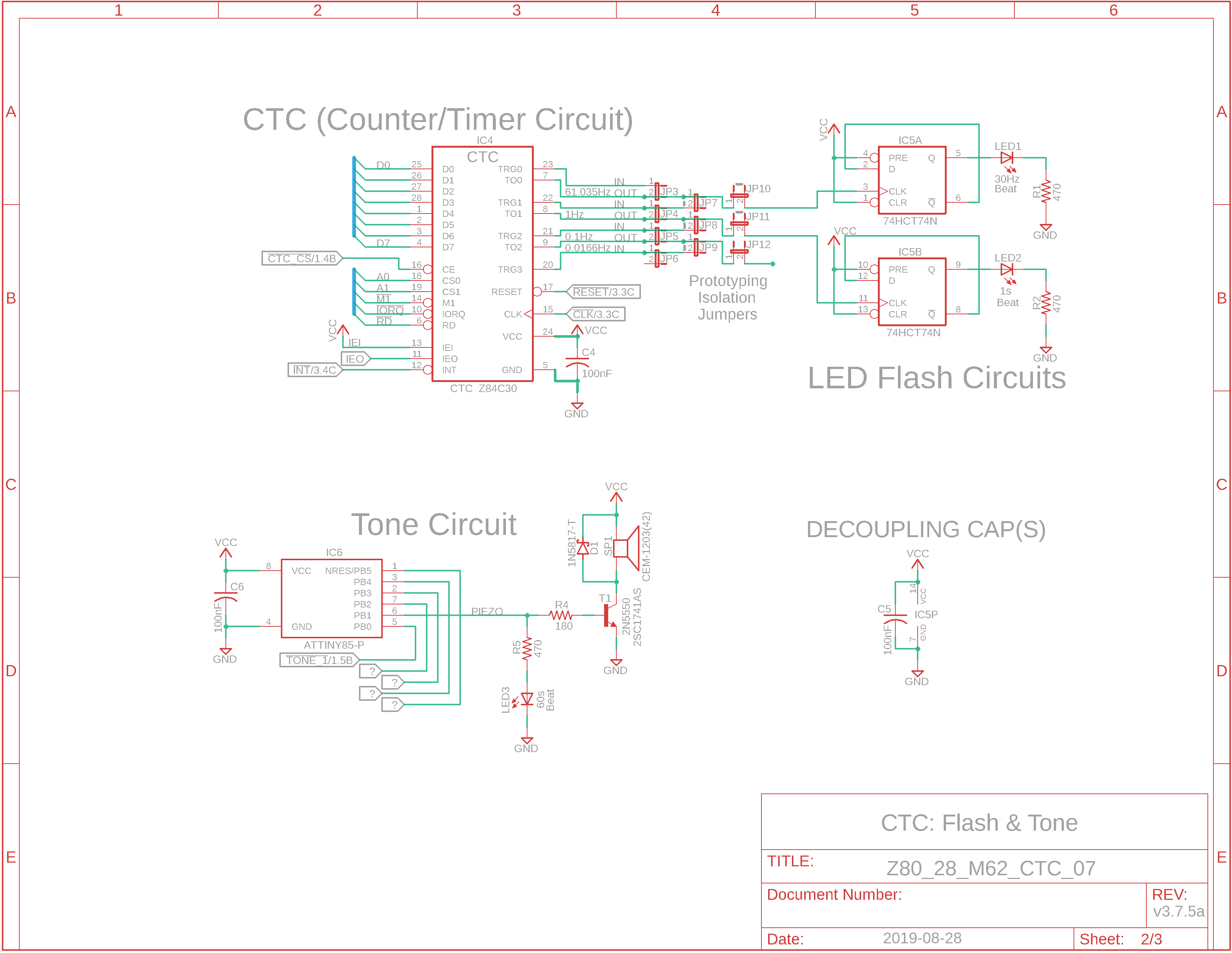
Eagle Schematic: LEDs & Tone Flasher
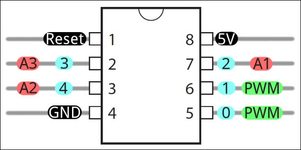
Diagram: ATtiny85 Pinout
Table: ATtiny85 Pinout D0 = pin 5 D1 = pin 6 D2/A1 = pin 7 D3/A3 = pin 2 D4/A2 = pin 3 D5/Reset = pin 1
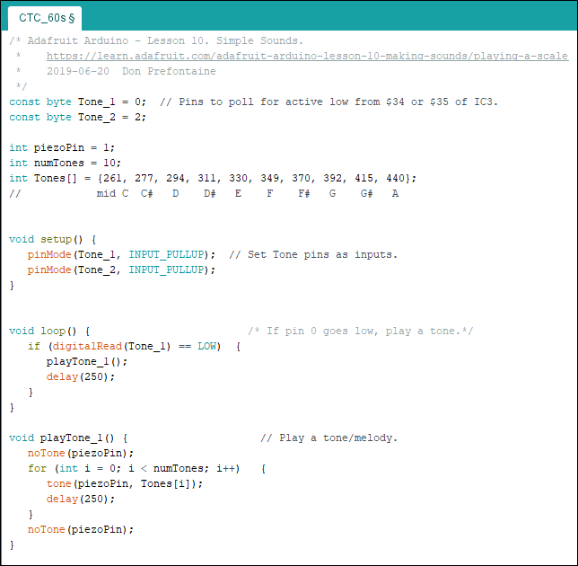
Arduino ATtiny85 Source Code: CTC_60s.ino
How-to Document: Program an Arduino ATtiny85 |
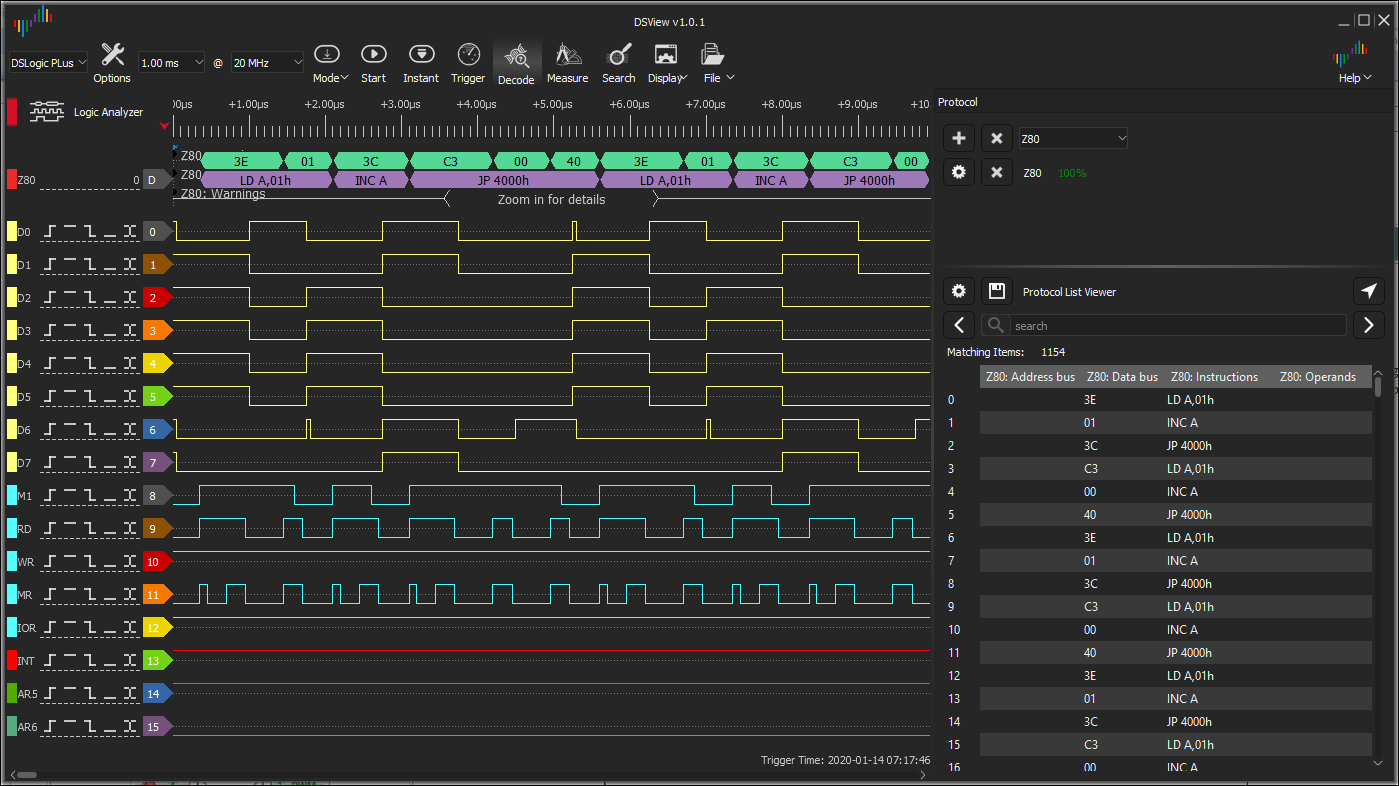
How do I know the Logic Analyzer is working properly? Here is the Z80 assembly code for Test_LA.asm. As you can see, it's very simple and should display well in your logic analyer:
0001
4000
.org $4000 0006 4003 .end
Load up and run the program Test_LA.bin at location $4000, then perform an Instant capture with the DSLogic Plus logic analyzer. Your results should resemble those of this screenshot; you can see the program run twice:
How do I setup the DSLogic-Plus DSView application? You can start by following this text guide verbatim: Setup_DSLogic-Plus_DSView-app_for_Z80.txt I've attached DSView v1.01 User Guide, too, in case you need it.
How the Z80/ATtiny circuit works: When an OUT instruction is sent to I/O address $34, a low signal is sent out IC1's pin 6 to IC6's input pin 5 (Arduino D0). In the second adjacent screenshot, IC6 the microcontroller is continually polling input TONE_1 for a low-going signal. When received, the corresponding tone/melody is sent out IC6's pin 6 (Arduino D1) to the piezo speaker/magnetic buzzer circuit; this should play a tone/melody once. Also, blue LED4 should be illuminated. The CTC is configured such that every time it receives an input on CH3 from CH2 - every 10 seconds - it decrements a counter of 6. When the counter reaches zero, an interrupt is triggered that causes the Z80 CPU to execute an interrupt service routine (ISR) at $0038 which sends an OUT instruction to address $34 that has been labeled TONE_1.
This is the Arduino C++ code that polls the microcontroller pin for low-going signals and plays the brief tone/melody:
If you wish the tone to play quicker, change the statements "delay(250)" to something smaller, like maybe 25ms instead of 250ms.
Question: How do I program an ATtiny85? a) Download the Arduino IDE (integrated development environment). b) Configure an Arduino Uno as an ATtiny programmer. c) Breadboard the Arduino ATtiny85 microcontroller to attach to the Arduino Uno. d) Use the Uno to upload a Bootloader to the ATtiny, then upload a test sketch like Blink e) Once you're certain all is well, load the adjacent sketch CTC_60s.ino and run it. Now your ATtiny is "permanently" configured to play the tone when it receives a control signal specified in the Z80 assembly program.
This is a bit of work if you are new to Arduino so I've include a document entitled Program_an_ATtiny85.txt that you can follow verbatim to make the job easier. Here's a link that can also be very helpful: High-Low Tech. And here's an Arduino link for programming the ATmega328 chip: https://www.arduino.cc/en/Tutorial/ArduinoToBreadboard |
![]()
Tags: DSLogic-Plus, DSView, Logic Analyzer, ATtiny85