|
Z80 Programming IV |
|
RAM - Filling a memory block with a single data byte |
|
Overview: Our first circuit involved NOPs. We breadboarded the circuit and it worked fine. We then burned the code to a ROM and verified our success with the simple code. The next circuit involved RAM instead of ROM. Well sort of: we wrote code for the ROM to fill a RAM memory block repeatedly with a single data byte. Let's have a look at the code, after a quick review of Z80 registers.
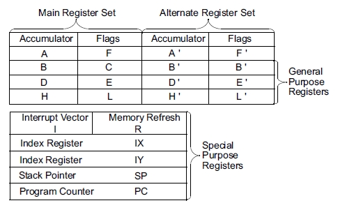
A Quick Review According to page 2 of the Z80 CPU manual, the 8-bit registers are paired together as 16-bit registers. From the diagram below we can see that 16-bit register BC is made up of 8-bit register B and 8-bit register C.
DE = D + E, HL = H + L, and AF = A + F. A is the Accumulator where most of our calculations and comparisons will take place, and F is the Flags register that lets us know if the Zero flag is set, if there was a carry from the low nibble to the high nibble, etc.
There are Index Registers, too, that are great for working with arrays.
There's the Program Counter that we've learned about, and there's a Stack Pointer which is a last-in-first-out (LIFO) memory area. You usually assign it to the top of RAM and it stores data temporarily. Typically we store a register's contents there so we can reuse the register briefly for something else. Register values are PUSHed onto the Stack and they are POPped off; order of operations is important because the Stack is like a popup stack of dinner plates you might see at a buffet restaurant. The kitchen help put the clean ones on top by pushing down on the stack, and you take one off the top for your lunch/dinner. You will not get a particular plate, just the next one available on the stack. So you can see that it's important to keep track of what you push on the stack and pop off. Here's an example: PUSH A, PUSH B, PUSH C. Now POP C, POP A, POP B. What just happened? A and B have traded contents because the only mechanism/person keeping track of the stack is you. Sooner or later this is going to byte you (pun intended) in the back side, so...
As if that's not enough, we even have an Alternate Register Set that can be invoked with a simple dedicated instruction.
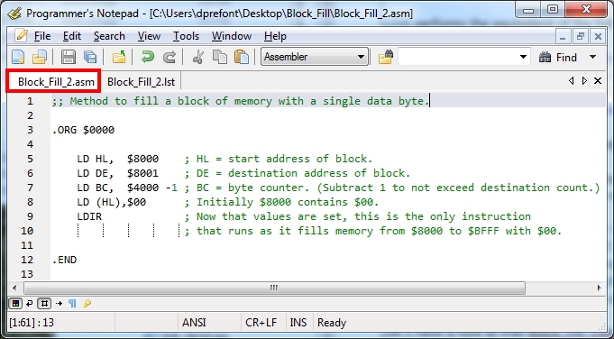
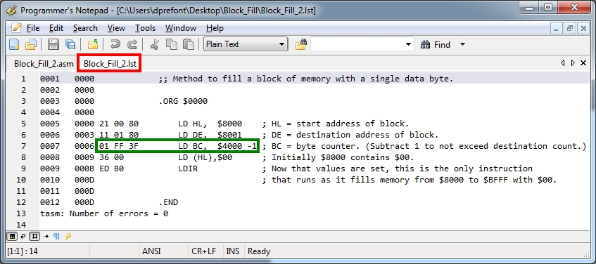
Show the code The object of the SRAM Test was to write a single byte repeatedly into a block of RAM. Here's the .ASM source code file as well as the assembled .LST listing file: This link will provide you with the source .ASM file, the .LST listing file, as well a .BIN file to burn to EEPROM.
How does it work? Being an 8-bit CPU, the Z80 can only move one data byte at a time. We fill location $8000 or HL with $00 and use LDIR to copy its contents to $8001 or DE. HL is incremented to $8001, DE is incremented to $8002, and BC is decremented by 1. In the next LDIR pass, we copy the contents of HL to DE, that is $00 from $8001 to $8002. We want the entire memory block from $8000 to $BFFF to be filled with $00. However, we started out with our destination, DE, numerically one higher than the source, HL. That means we will write $00 into $C000 which is not what we want. To work around that, line 7 in the .ASM file performs a simple calculation, "$4000 - 1", before the result is handed to BC, our byte counter. You can see the result in the .LST file in the machine code: "LD BC" = "01" and "$4000 - 1" = "3FFF" shown in Little Endian format with the low order byte (FF) listed first at location 07 and the high order byte (3F) listed next at location 08 in the program.
|