|
Z80 Programming V-a |
|
UART Serial Interface |
|
Page a |
|
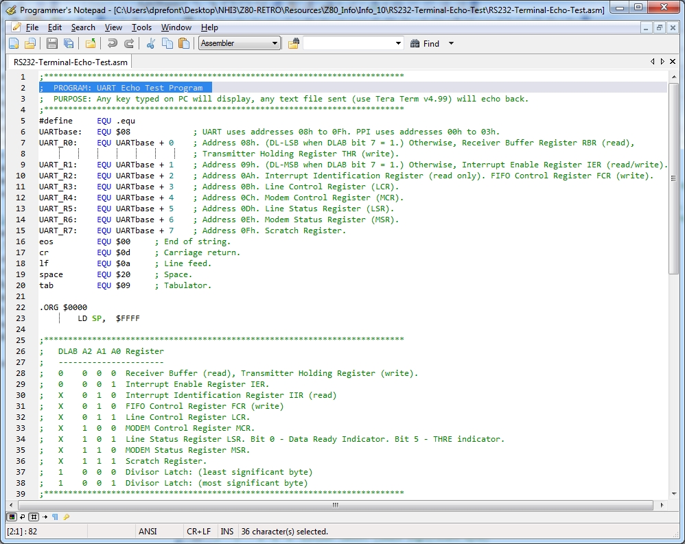
So how do we make this work? We'll start by looking at the code found in RS232-Terminal-Echo-Test.asm. It is best if you have already reviewed Z80 Circuits II because it contains considerable technical info on the circuit, the UART, etc. Using Programmer's Notepad, you can see there is quite a bit of reference information found in the first 39 lines. The UART-specific EQUates for the UART registers and functions are defined in lines 6 to 15.
UART Init:
In line 6 we state the base address for the UART is 8, then 8 registers are identified as the base address plus a value starting at 0. That means we have UART_R0 through UART_R7 with UART_R0 being address 8, UART_R1 is address 9, etc. Each of those 8 registers has a role or roles to play. Starting in line 26 we show the Address Bus lines A2 to A0 and the derivation of the 11 UART registers and functions from those 8 address combinations, 00 to 08. This is possible because some of the registers perform dual duty: they are used during both UART initialization and data transfer.
Line 32 shows the LCR, the Line Control Register, UART_R3. LCR is an 8-bit register and its bit 7 has a special name and purpose. It's called the DLAB bit or Divisor Latch Access Bit. The DLAB itself, a 16-bit register, is composed of the DLM and DLL. Initially during configuration, the DLAB bit is set to a 1 so that the DLL (least significant byte) and DLM (most significant byte) can be used to set the baud rate. Once the baud rate config is completed during UART Init, the DLAB is set to 0 so the Tx and Rx buffers can be used to move an internal byte to external bits, or the reverse action of assembling external bits to an internal byte. The DLAB is no longer needed for configuration.
In line 43+ of the code starting in the second screenshot below, you can see $80 being loaded into the LCR (UART_R3) via the OUT instruction: address $0B (UART_R3) is put on the Address bus with IORQ asserted and $80 is sent on the Data bus. This will cause the UART to go into configuration mode and the DLAB will be temporarily enabled. In line 47, $60 is sent to address $08 (UARTbase + 0, DLAB DLL) and $00 is sent to address $09 (UARTbase + 1, DLAB DLM), thus the DLAB (DLM + DLL) contains $0060. As the comments in line 47 indicate, we have set the baud rate to 1200bps. If we had used a smaller value, the baud rate would have been higher but we want you to see the characters you type being echoed back to the terminal screen hence the reason for the slower speed. The final part of the UART initialization is to set the line protocol. Doing so will also reset the DLAB flag, concluding initialization. The value $03 means 8N1 or 8 bits Data, no Parity, one Stop bit. Lines 43+ were used to initialize the UART. Line 56 simply clears the Z80 accumulator, register A. |
|
UART Get a Character: The Line Status Register, UART_R5, tells us if a character has been received. It does so by testing bit number zero. In line 63, we read the LSR into Z80 register A and then test bit 0. If it's a 0, then no character has been received. If it's a 1, then the bits received from the wire have been assembled into a byte in UART_R0. (UART_R0 was used as the DLAB DLL during Init but now it's the receive buffer.) Line 67 shows the received character being copied into Z80 register B.
UART Put a Character: Now that we have a character from the user stored in Z80 register B, we're going to output it to the terminal screen but first we have to check if the UART is ready to send. To do so we read in UART_R5 again but this time we test bit 5 instead of bit 0. If bit 5 is a 1, then the Data Ready indicator is set indicating we can send the byte. The character we received and stored in Z80 register B is now output to the UART's Transmitter Holding Register (THRE) by copying B into A and then sending it out UART_R0 in line 78.
The program repeats itself in line 80 by jumping back to line 56 where we clear register A. Thus every character you type should be echoed to your terminal screen. Try holding down a key to see how "fast" 1200bps is.
In summary: - We set the LCR to initialize the UART - UART_R0 and UART_R1 will set the DLAB for baud rate configuration - UART_R3 will set the line protocol configuration of 8N1. Init is now complete - We check the DR Indicator of UART_R5 to see if a user has sent a character, then store it in Z80 register B - We check the THRE indicator of UART_R5 to see if the UART is ready to echo the character to the screen. If so, the stored character in Z80 register B is sent out UART_R0 - UART_R0 is used during Init to set the baud rate, and is both the incoming and outgoing buffer once Init is complete |

