|
Input/Output Test II |
|
I/O Output Test Using an 82C55A PPI or Equivalent |
Videos |
|
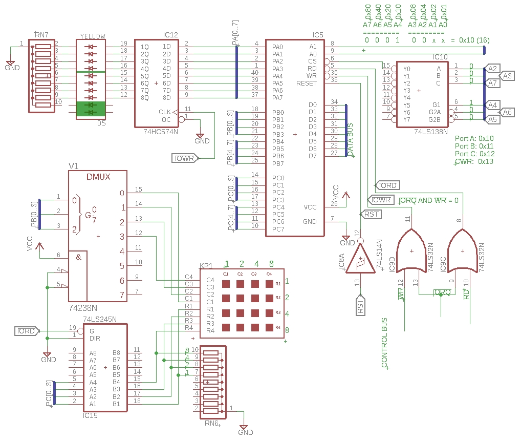
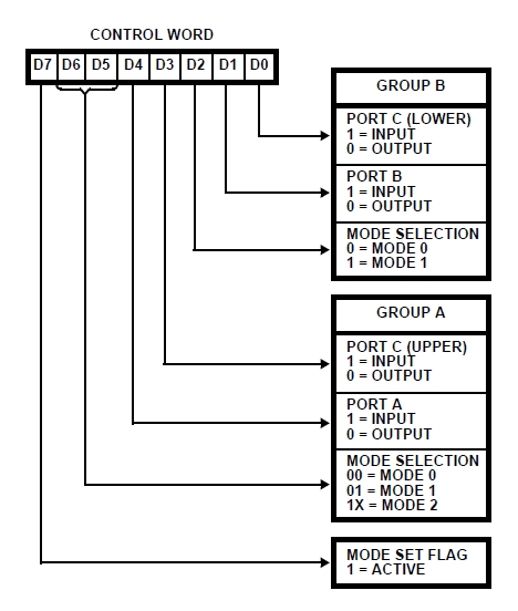
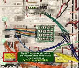
Overview: - In this test, we'll read from a 4x4 matrix keyboard and output each key press position on a bar graph LED - The adjacent schematic shows the 8255 configuration we were working with in Input/Output Test I but new components have been added: 74238 non-inverting demultiplexor, 74245 output driver, and a 4x4 matrix keypad - The Configuration Word Register for the 8255 is setup such that Port B is an output to the '238 demux to the keyboard columns, Port C in an input from the keyboard rows, and Port A is an output to the bar graph LED - Only Port B lines 1 and 2 are used for a 2-bit signal to drive the 4 columns. If we apply the binary values 00 or 01 or 10 or 11, i.e. decimal values 0 to 3, then the 4 demux output lines (pins 15 to 12) will output the decimal value. For instance, when binary 00 is sent as input to the demux, only line 15 has a 1 asserted at the output. 01 will output a 1 on only pin 14, 10 will output a 1 on only pin 13, and 11 will output a 1 on only pin 12. The other lines are not used. We could use them if we had a 64-key keypad but there are other ways of reading input, too
How does the circuit work? - As mentioned above, we will send binary values 00 to 11 on demux pins 1 and 2, one value at a time. Each time we do, we'll read in the first 4 lines of Port C. - As an example, if a key, the vector of column 1 and row 1 is pressed, then the circuit which is normally low due to the pull-down resistor will instead be high and we'll read a value of 1 for column 1 - If, while sending a 00 for column 1 and subsequently reading the rows, we press a key at the vector of column 1 and row 2, then a value of 2 will be read. For row 3, a 4 will be read. For row 4, an 8 will be read - The left-most column of keys pressed sequentially from top to bottom should read 1, 2, 4, 8 - The top-most row of keys pressed sequentially from left to right should read 1, 2, 4, 8 - With 4 columns and 4 rows this gives us 16 possible key presses
How do we let the user know which key was pressed? - We have an 8-position LED bar graph. We could use the 4 left-most LEDs to represent the columns and the 4 right-most LEDS to represent the rows - The binary weighting of the LEDs from left to right would be 8, 4, 2, 1 for both column and row. So if the key press is column 1, row 1, then the LEDs should read as follows: 0001 0001. If the key press is column 4, row 4, then the reading should be 1000 1000. - We will read the first column first. If a key is pressed, the row value will be 1 or 2 or 4 or 8, depending on whether the key was on the first to fourth row. This is what we are doing in the code below in line 15 with the label Col1 which is short for Column 1. - In the code below, we send hex 0 to Port B in line 15, and then we read in Port C in line 17. The AND is used to remove the high order nibble leaving us just the lower nibble which is compared to 00. If no key is pressed, then the value should still be 0 from the pull-down resistor. Line 20 forces us to try Column 2 where we send a hex 1 in line 23. If no key is pressed, we move on to Column 3 with hex 2 in line 31. Again, if no key is pressed, we move on to Column 4 with hex 3 in line 39 - Assuming a key is pressed while we are in Col1 that starts on line 15 of the code below, then line 20 will be skipped because the value will be 1 or 2 or 4 or 8 depending on which row under Column 1 was pressed. To indicate t the key was pressed in Column 1, we need to mark the first bit of the high order nibble of the 8 LEDs; example: 0001 xxxx. That is why in line 21 we add 0x10 to the value of the key that was pressed in Column 1. Again, if it's the first row, the value read on Port C would be a 1. If the second row, it would be a 2. Third row, 4. Fourth row, 8. - If the key pressed vector was Column 1, Row 4, then 0x10 added to 0x08 would give us the value 0x18. In binary, that would be 0001 1000. Wherever there is a binary 1, we would expect that LED segment to be lit - To actually display the pressed key, we would need to jump to the display routine (line 22 takes us to line 47 in our code) to output the value 0x18 in register A from our example, to the LEDs connected to Port A - Once we have output the LED vector value for a pressed key, the program jumps to Cols where it repeats itself, working through all four columns sequentially looking for a key row press
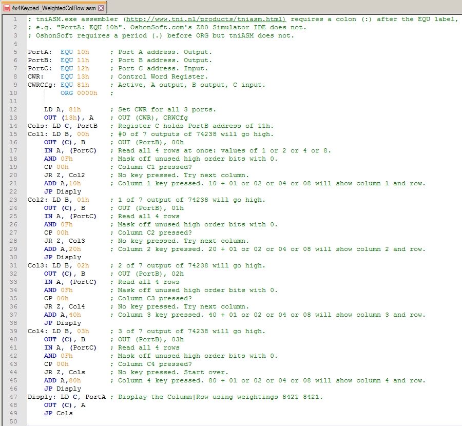
Examine the assembly code below for I/O Output Test II: -
4x4Keypad_WeightedColRow.asm is documented below:
How do I get this program onto my EEPROM? Use the Z80_eprom_programmer.ino file. It contains everything you need in line 61 that begins with "byte data[]". Line 60 shows comment characters, //, indicating this line of code is for the 4x4_Keypad program. You can see the other programs above these two lines commented out as well. |
Input/Output Schematic
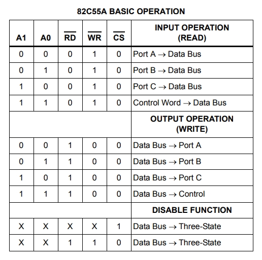
82C55A PPI, Programmable Peripheral I/O Device
Video: Z80 keypad input and bar graph LEDs output
Clicking the thumbnail gif above will provide an HD video (11.5MB, .mp4 format)
|