![]()
|
Aduino (Cube) M4 MBC |
| PCB Circuits (click to enlarge) | Circuits and Info |
|
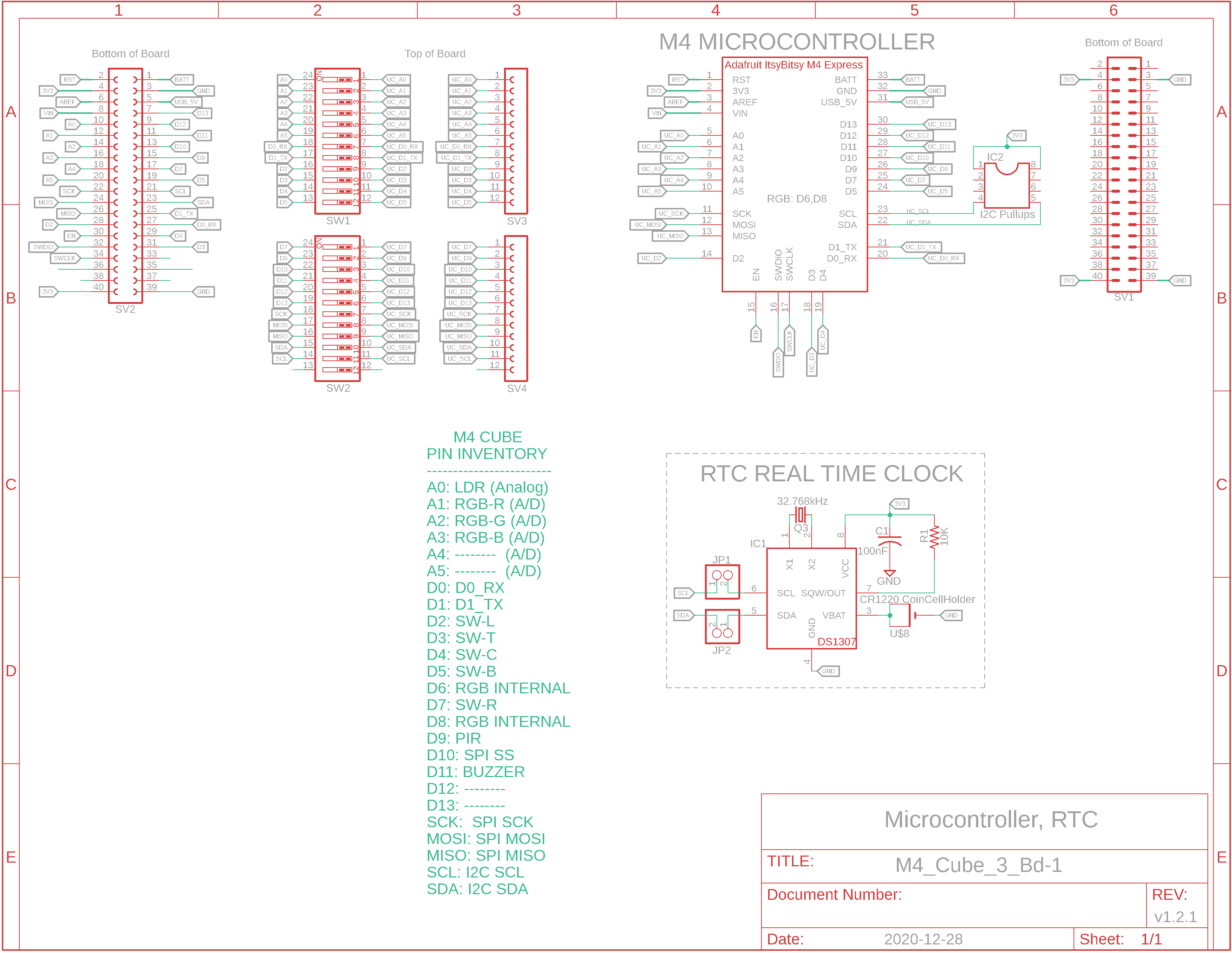
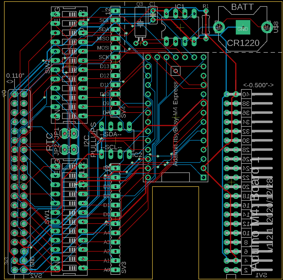
Eagle CAD: M4 Cube Bd. 1 Schematic a
Eagle CAD: M4 Cube Bd. 1 Schematic b
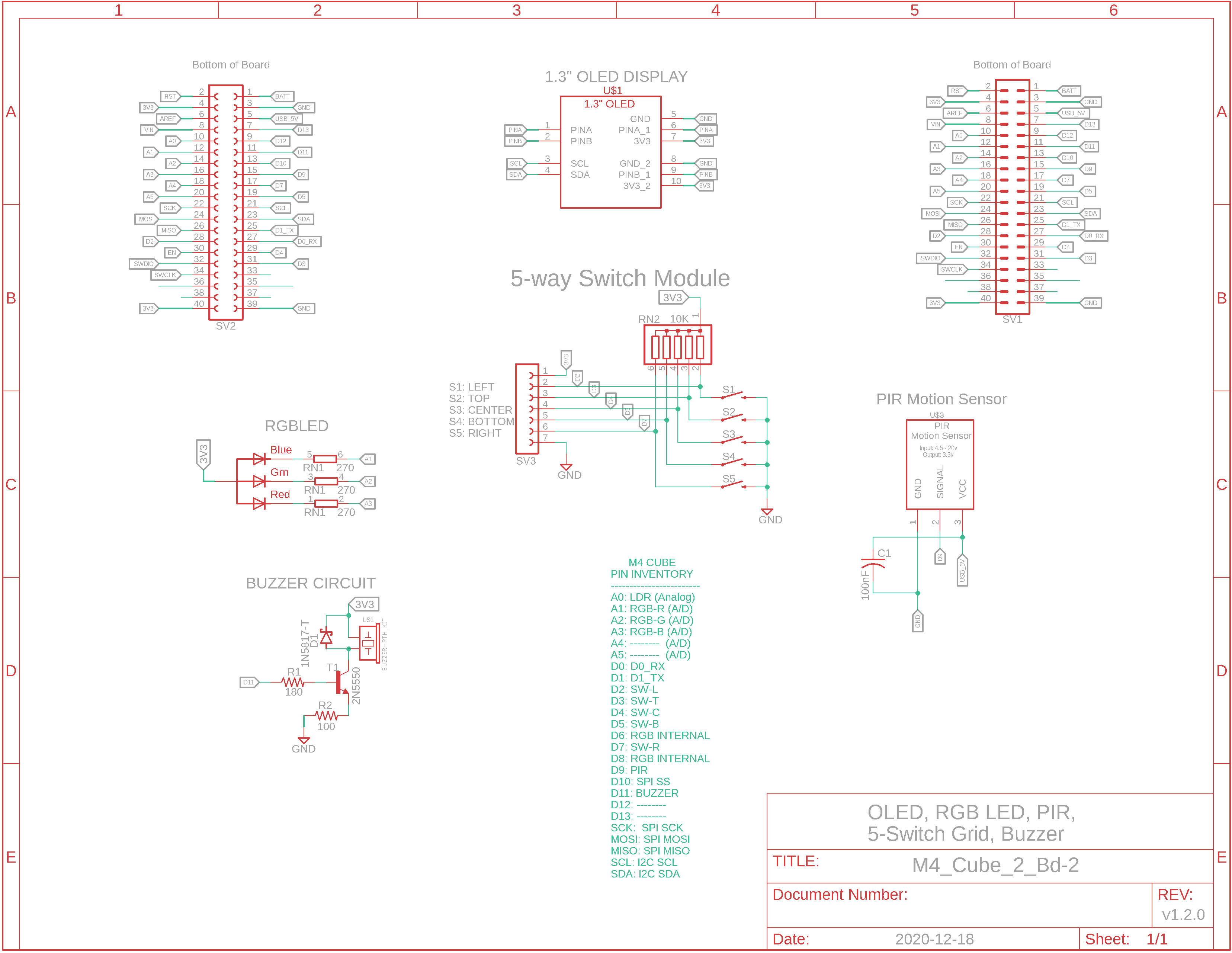
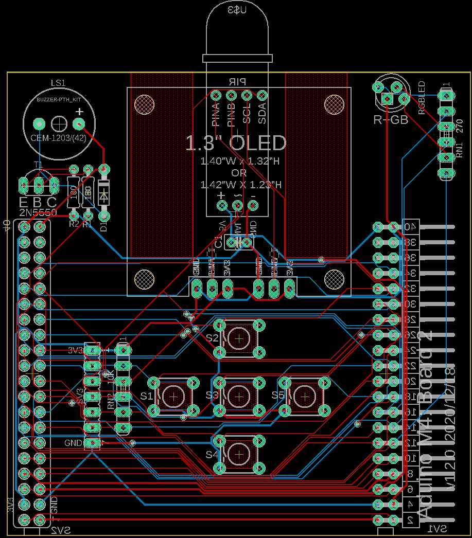
Eagle CAD: M4 Cube Bd. 2 Schematic a
Eagle CAD: M4 Cube Bd. 2 Schematic b
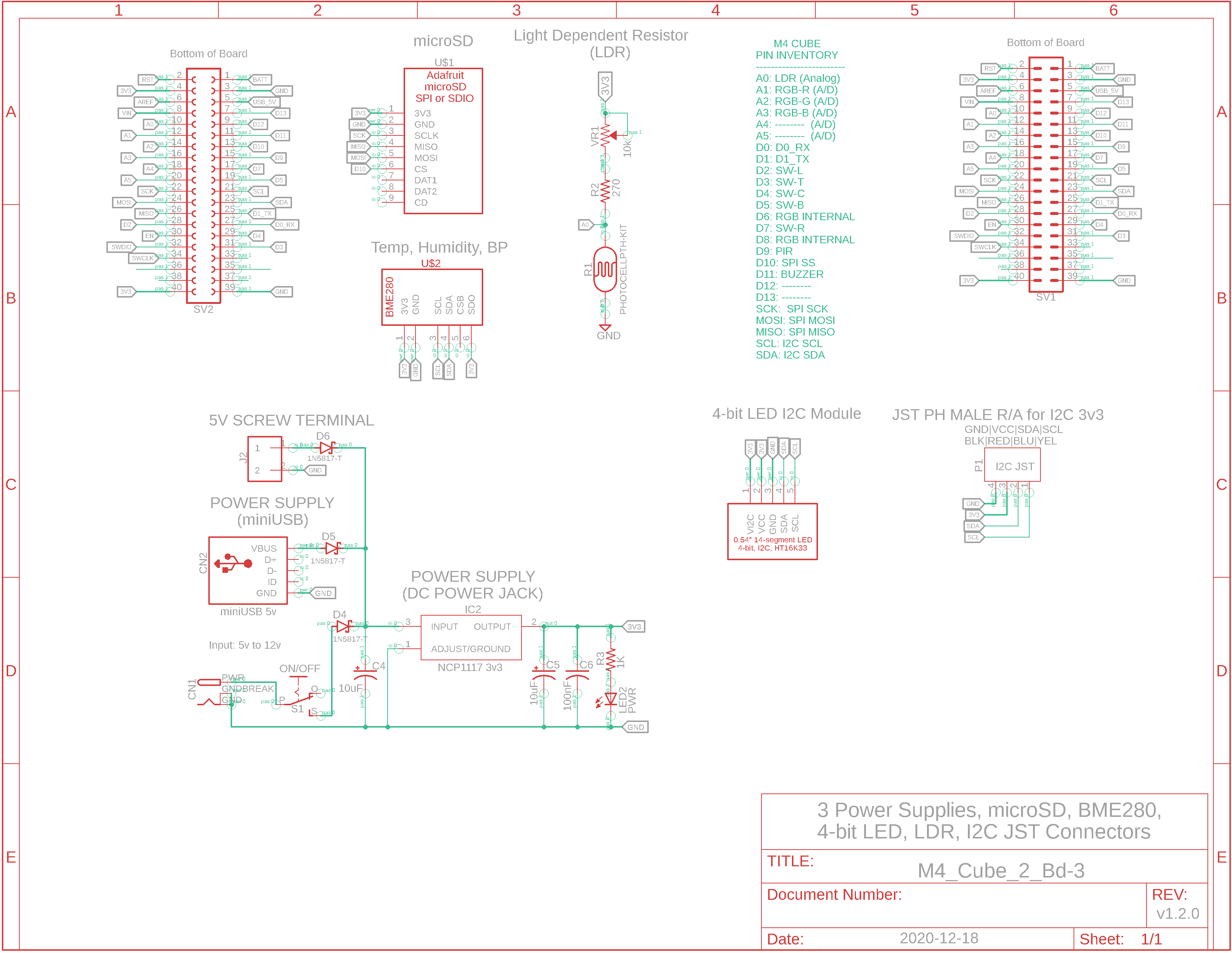
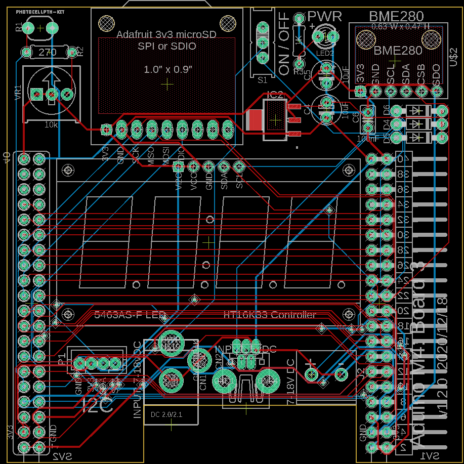
Eagle CAD: M4 Cube Bd. 3 Schematic a
Eagle CAD: M4 Cube Bd. 3 Schematic b
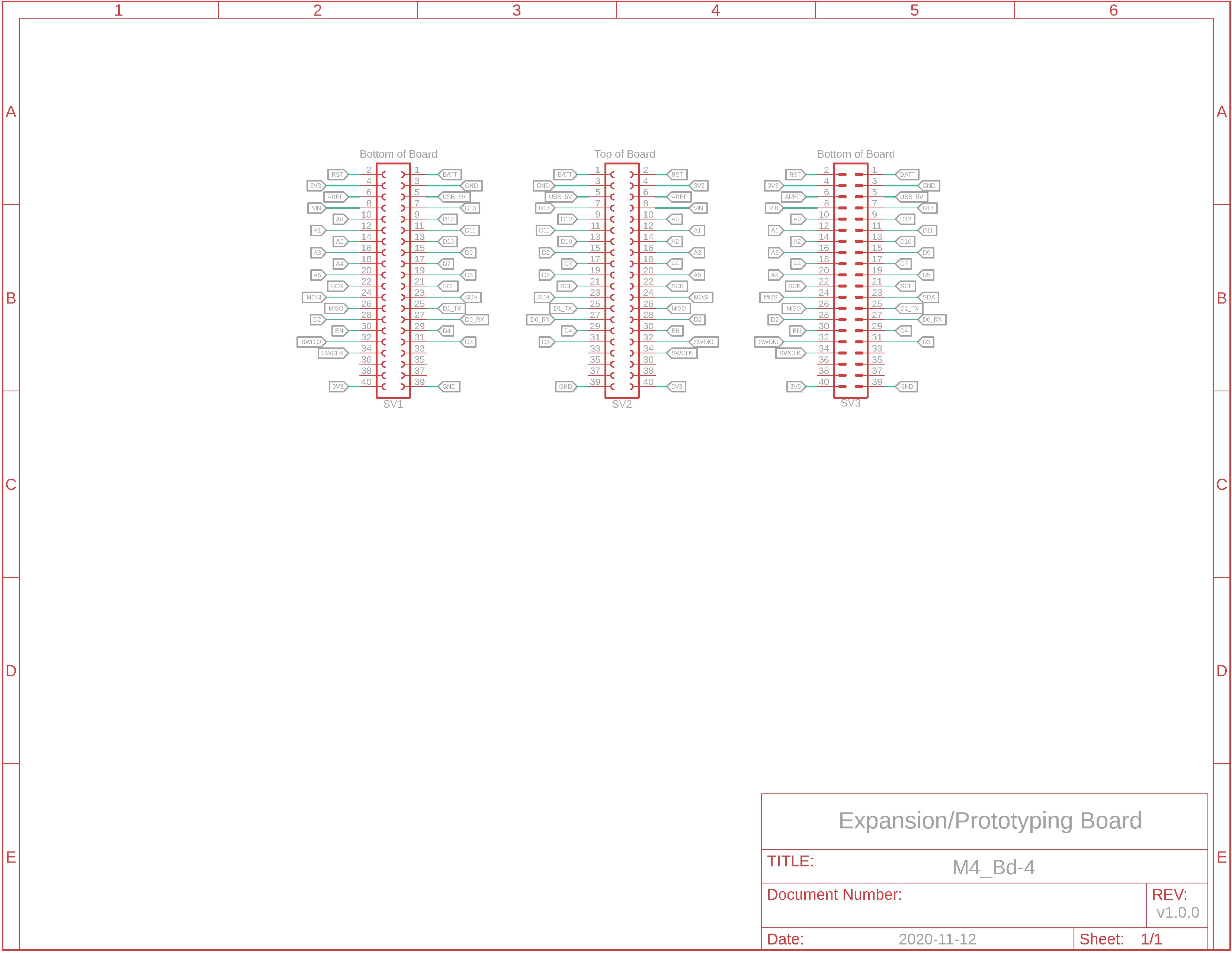
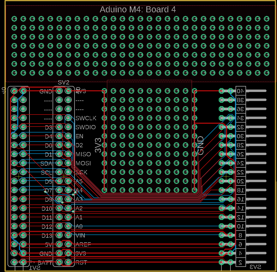
Eagle CAD: M4 Cube Bd. 4 Schematic a
Eagle CAD: M4 Cube Bd. 4 Schematic b
|
Overview The first weather station we built was comprised of a small Aduino base board and an expansion board with display and sensor on it. The second weather station was similar but built as a single board computer (SBC). This third weather station will be a multi-board computer (MBC) built with the Adafruit ItsyBitsy M4 Express microcontroller board. The devices on the MBC are strictly 3.3v DC but you can power the "M4" with a 5v DC USB cable (to your PC) or "wall wart".
Weather Station There are several resources installed on the MBC to function as a type of weather station that can provide: - display of the current stats: temperature, humidity and barometric pressure values - calculation of Dew Point and Humidex - data logging to a microSD card
Microcontroller Resources The M4 Express uses a Microchip ATSAMD51G 3v3 microcontroller with the following resources: - 120MHz, 512KB Flash for program storage, 192KB dynamic SRAM for global variables, 2MB SPI Flash for CircuitPython code storage if you're not using the Arduino IDE (apparently you can switch back and forth between these two programming languages). This is soooo much more than the original Atmel ATmega328 and it means you can finally run graphics on the OLED without draining all of the SRAM - native USB for programming and serial monitor debugging - I2C and SPI serial ports - 3.3v operation, reset button and pin - many, many more features. Check out the Microchip datasheet or Adafruit's .pdf on the ItsyBitsy M4 Express microcontroller breakout board
I2C Devices like the 1.3" OLED and BME280 sensor utilize I2C for communication. Additional I2C devices can be connected via the two JST 4-pin connectors on Board 3. Here are links for cables and connectors: - JST cable - JST
connector
MBC Features: All of the functions present on the ATmega328 SBC are present on this 4-board M4 Cube MBC, and there is one digital pin (D13) left over for your own development ideas on Board 4. Additionally, all of the pins in use on the uC can be switched out so you can use the pin for other purposes.
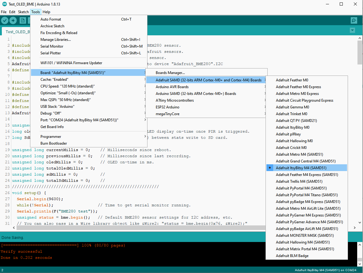
USB programming and power Arduino IDE should be configured for "Adafruit ItsyBitsy M4 (SAMD51)". Here is a link to installing and configuring the device The MBC can be powered via 5v miniUSB (the M4 converts it to 3.3v) or via a terminal block. Diodes D1 through D3 on board 3 will help with the correct polarity.
Devices/Modules Included: - USB programming/power, separate USB power (5v, <500mA), 3.3v 2-wire screw terminal, 5-12v barrel connector jack - Built-in RGB DotStar LED on M4 board, RGB LED on Board 2 - Available LiPoly backpack to attach a rechargeable battery to the M4 Express uC module - 128 x 64 OLED monochrome display - microSD card module for data logging - DS1307 Real Time Clock with battery backup - BME280 Temperature/Humidity/Barometric Pressure module - 5 tactile switches for menu configuration or program operation - LDR light detecting resistor - Motion sensing Passive Infrared (PIR) sensor, could be used to sense movement to enable the OLED display, etc. - Buzzer for playing tones, etc.
Sketches Many of the sketches you used for the Base/Expansion board Aduino and the SBC Aduino have been changed for the M4 Cube Aduino to accommodate the new pin layout so it's best to use them. Remember that the I2C (A4, A5) and hardware SPI (D11, D12, D13) pins are available for your assignment because the aforementioned are now dedicated pins and named as such: SDA, SCL and SCK, MOSI, MISO. As usual, the sketches are Arduino code based C++. If you decide to run CircuitPython instead, then you will need to know about the CircuitPython Boot Sequence for the Adafruit ItsyBitsy M4 Express module: https://learn.adafruit.com/assets/75708
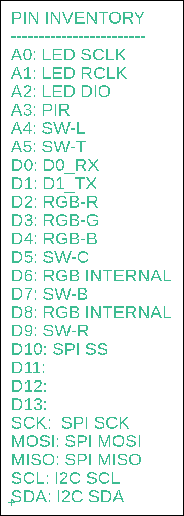
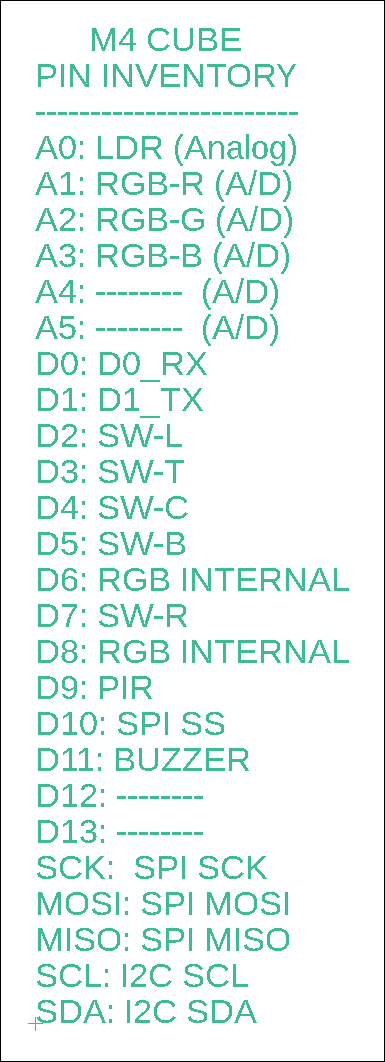
The LDR requires an analog pin to be read so we'll assign that to A0. The 3 RGB pins are digital but if you wish to lower the intensity, etc., then you'll need analog pins to do so. They have been assigned to A1 to A3. Analog pins A4 and A5 are available for assignment. D0 and D1 are traditionally used for Rx and Tx so we'll leave them alone. D6 and D8 are used internally for the tiny onboard addressable RGB LED. That means we do not have 5 consecutive pins for the 5-switch button array so we'll use D2 to D5, and D7. D9 we'll use for the digital PIR motion sensor. D10 is traditionally used as the SPI SS for the microSD device so we'll stick with that. D11 is used for the buzzer. Well, that leaves D12 and D13 available, including as other SS pins for other SPI devices.
M4 Express Pin Resources Allocated OLD NEW
Arduino IDE Configuration
BOM1 (Bill of Materials, modules are not included)
|
|
|
|
![]()
Tags: Arduino-type Microcontroller, ATSAMD51G
![]()