![]()
|
Aduino ATmega328P SBC |
| PCB Circuits (click to enlarge) | Circuits and Info |
|
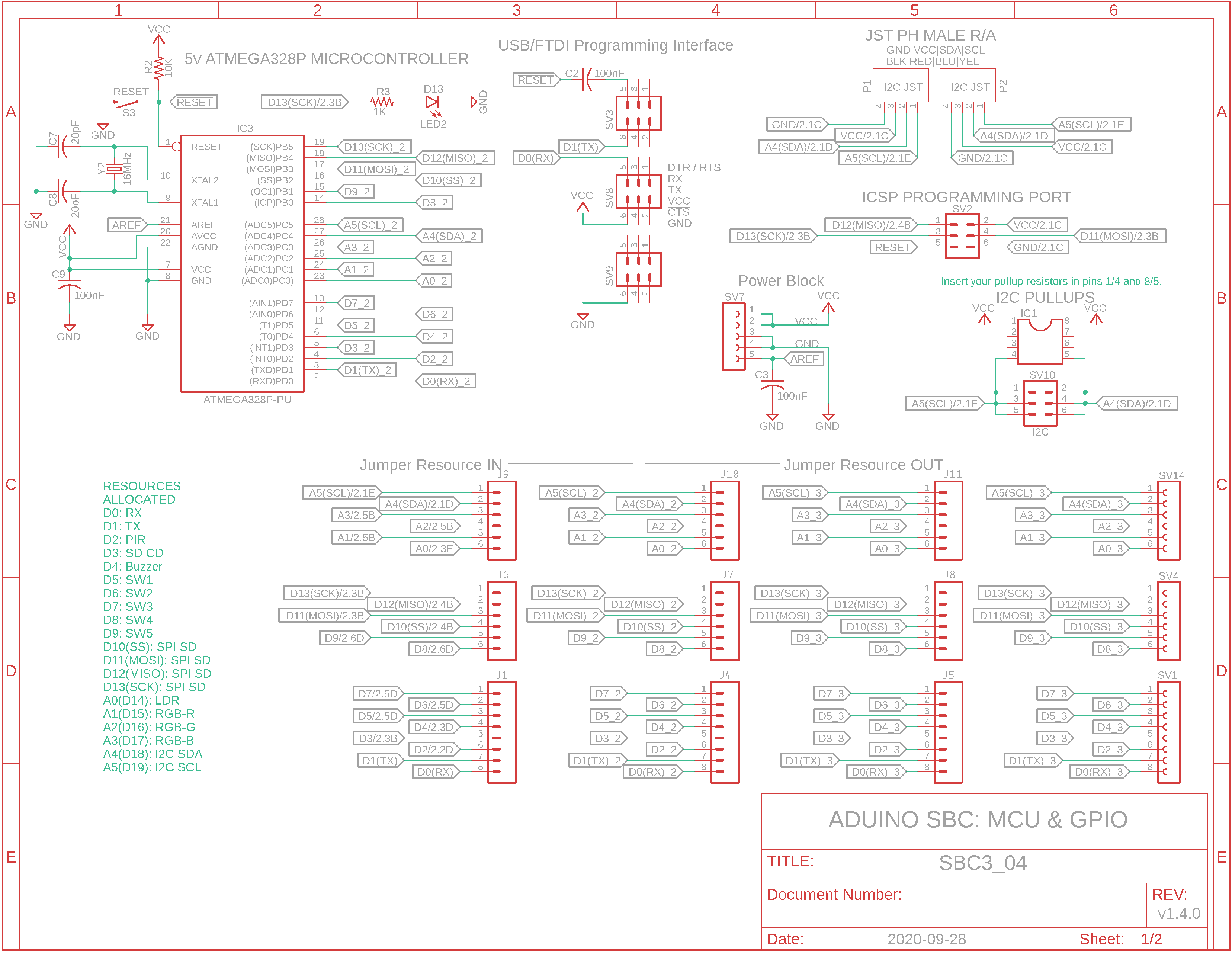
Eagle CAD: Microcontroller Schematic 1
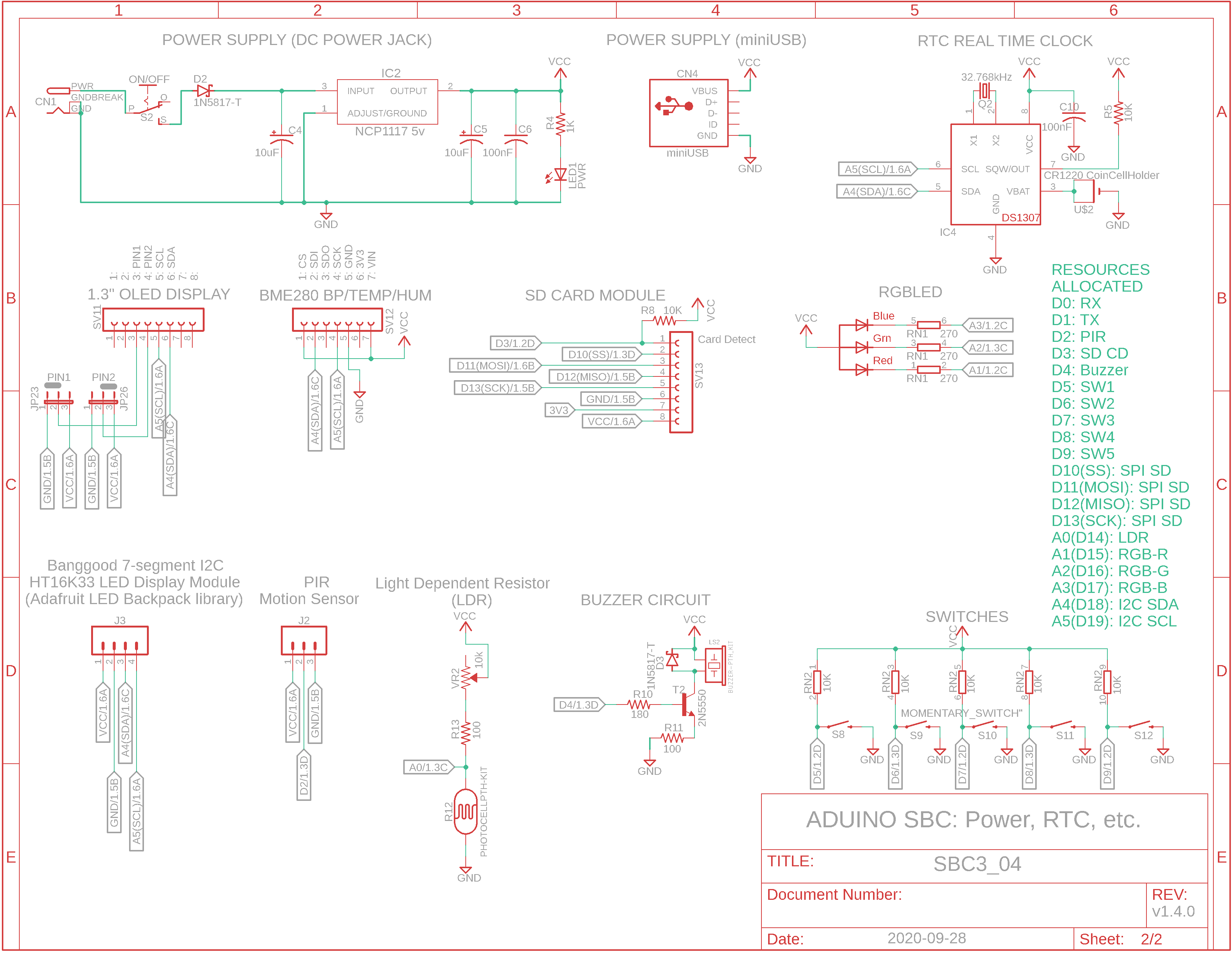
Eagle CAD: Microcontroller Schematic 2
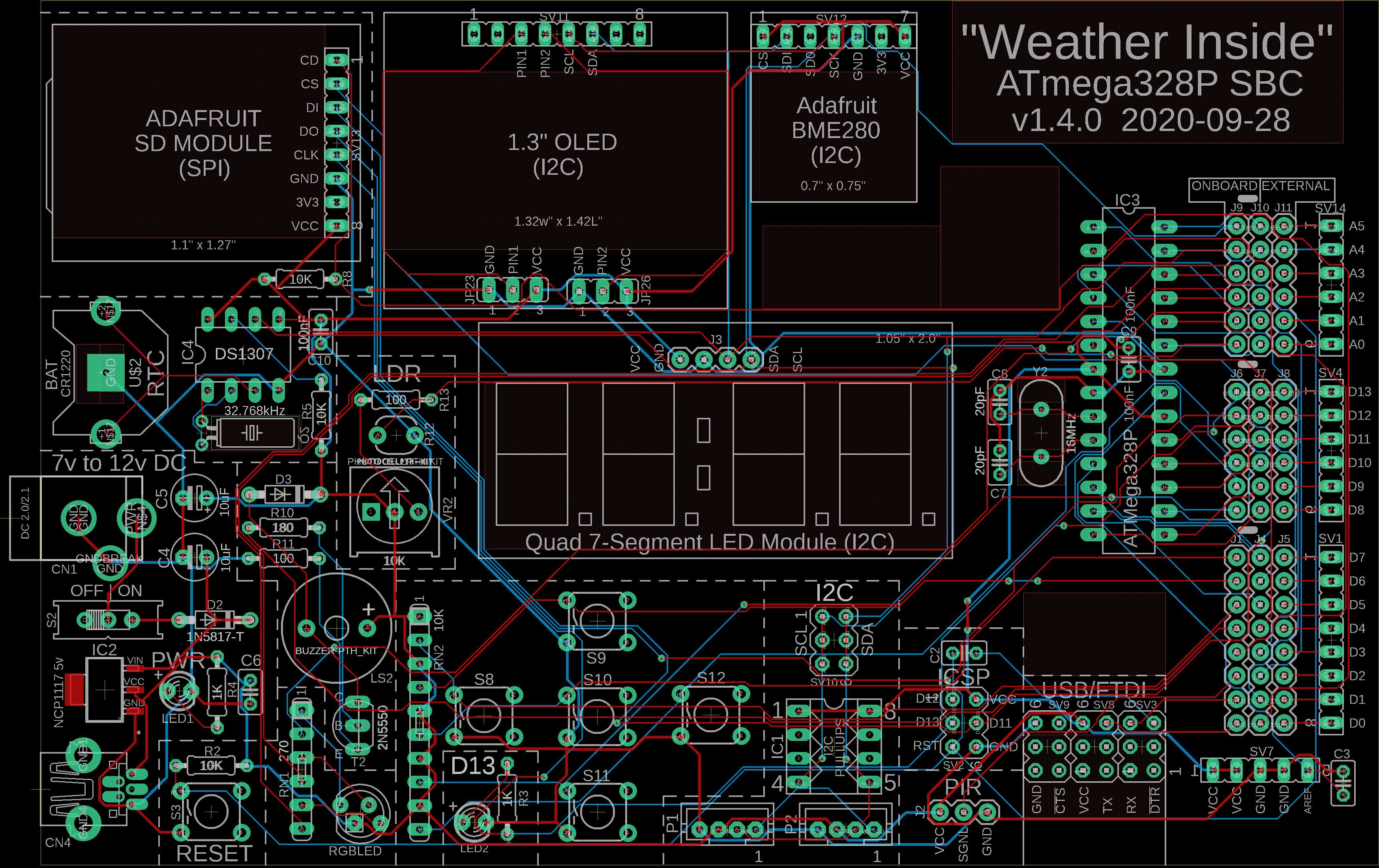
Eagle CAD: Microcontroller Schematic 3
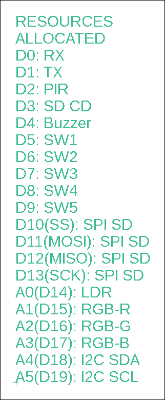
ATmega328P Resources Allocated
(Bill of Materials; modules are not included)
Working SBC (Click for a short video)
|
Overview The first weather station we built was comprised of a small Aduino base board and an expansion board with display and sensor on it. This second weather station will be similar but on a single board, hence the term single board computer or SBC as it's commonly known.
SBC Flexibility The SBC will be a little more flexible as to what you can do with it because all of the 20 GPIO pins from the ATmega328P microcontroller can be jumpered out via jumpers JP01 to JP20. As an example, if we only wished to run the PIR motion sensor on I/O pin D2, then we would move all of the jumpers except D2 from the left/center position to the center/right position.
I2C
Devices like the OLED and BME280 sensor utilize I2C for
communication. Additional I2C devices can be connected via SV10 or
the two side-mounted JST connectors. Near the JSTs is a 4/8-pin
socket used to hold your I2C pullup resistors. With minimal devices
using the bus, you could try 1K resistors. As more load is added,
you would need to increase the resistance to a max of 10K. The
resistors are connected between IC1 socket pins 1 & 4 and 5 & 9. Weather Station There are several resources installed on the SBC to function as a type of weather station that can provide: - temperature - humidity - barometric pressure - humidex values - display of the current stats - data logging
Microcontroller Resources Microchip ATmega328PU 5v microcontroller: - 32KB Flash for program storage, 2KB dynamic SRAM for global variables and 1KB EEPROM for config storage - I2C byte-oriented serial interface - SPI serial port - 6-channel 10-bit A/D converter - programmable watchdog timer - 3 timer/counters - 1.8v to 5.5v operation
SBC Features: - Separate USB-FTDI programming: Arduino IDE should be configured for UNO - "Wall-wort" 7v to 12v DC power (standard 2.1mm inner diameter, 5.45mm outer diameter male plug) - DS1307 Real Time Clock with battery backup - 20-pin external expansion connector: onboard devices like LEDs, PIR, SPI, etc. can be jumpered in (INTERNAL setting) or jumpered out (EXTERNAL setting) so other devices can use the same Arduino digital or analog pins - Classic D13 LED commonly used with Blink.ino sketch - standard SPI interface - multiple I2C interfaces: 5v via female connector, 3v3 via JST connectors - 5v to 3v3 level shifting for just I2C connectivity
Devices/Modules Included: - USB-FTDI (5v) programming - 128 x 64 (3v3) OLED monochrome display - SD card module for data logging - Adafruit BME280 (3v3/5v) Temperature/Humidity/Barometric Pressure module - 5 tactile switches for menu configuration or program operation - 3-colour RGB LED - Motion sensing Passive Infrared (PIR) sensor (5v), could be used to sense movement to enable the OLED display, etc. - Light Decreasing Resistance (LDR) sensor - Buzzer for playing tones, etc. - Banggood Quad 7-segment LEDs or Adafruit module (5v) for bigger display of temperature, etc.
Sketches Use the same sketches you did for the Base/Expansion board Aduino. |
![]()
Tags: Arduino-type Microcontroller, ATmega328P
![]()