![]()
|
Test Your Cube M4: Board 1 |
| Circuit Tests (click .gif for video) | Test: Board-to-board Connectivity, uC, I2C, RTC |
|
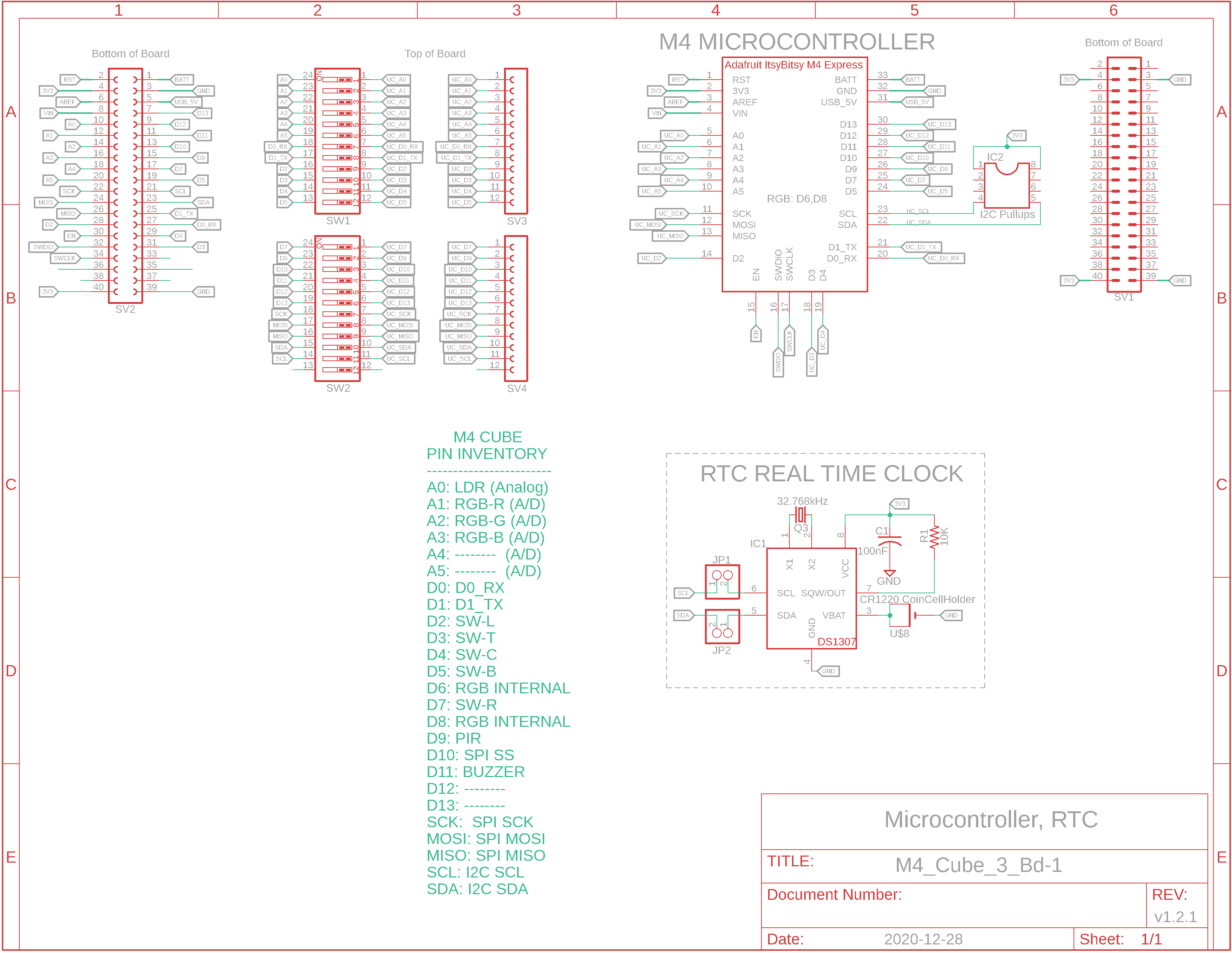
Eagle CAD: System Bd. 1 Schematic A
Eagle CAD: System Bd. 1 Schematic B
Video: 3_LEDs.ino Sketch Running
4 Connected Boards Rotated (Click for Video)
|
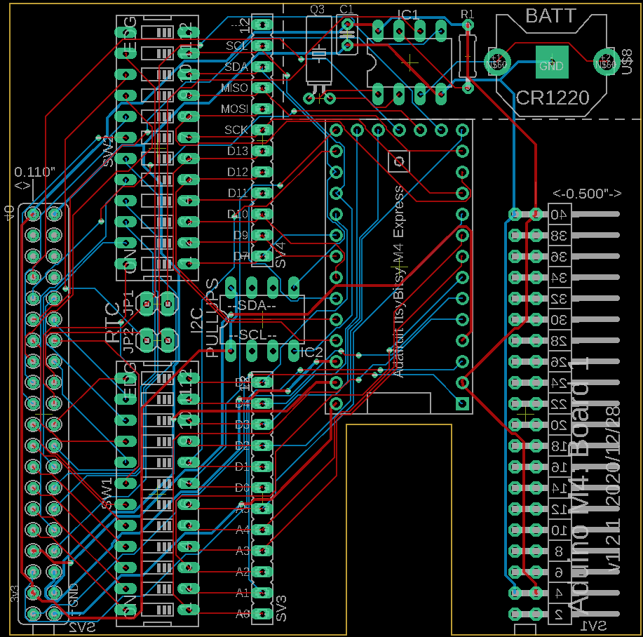
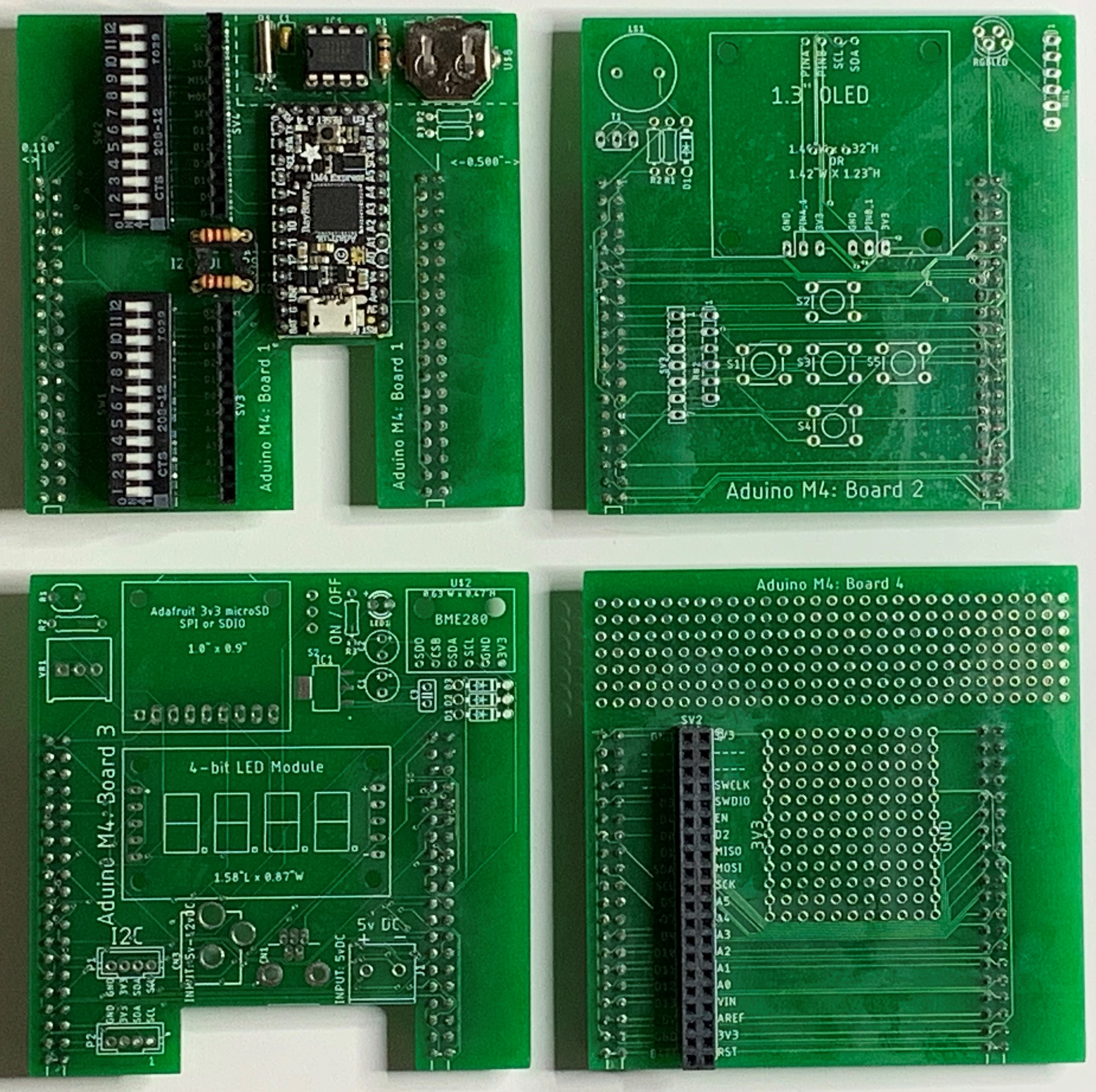
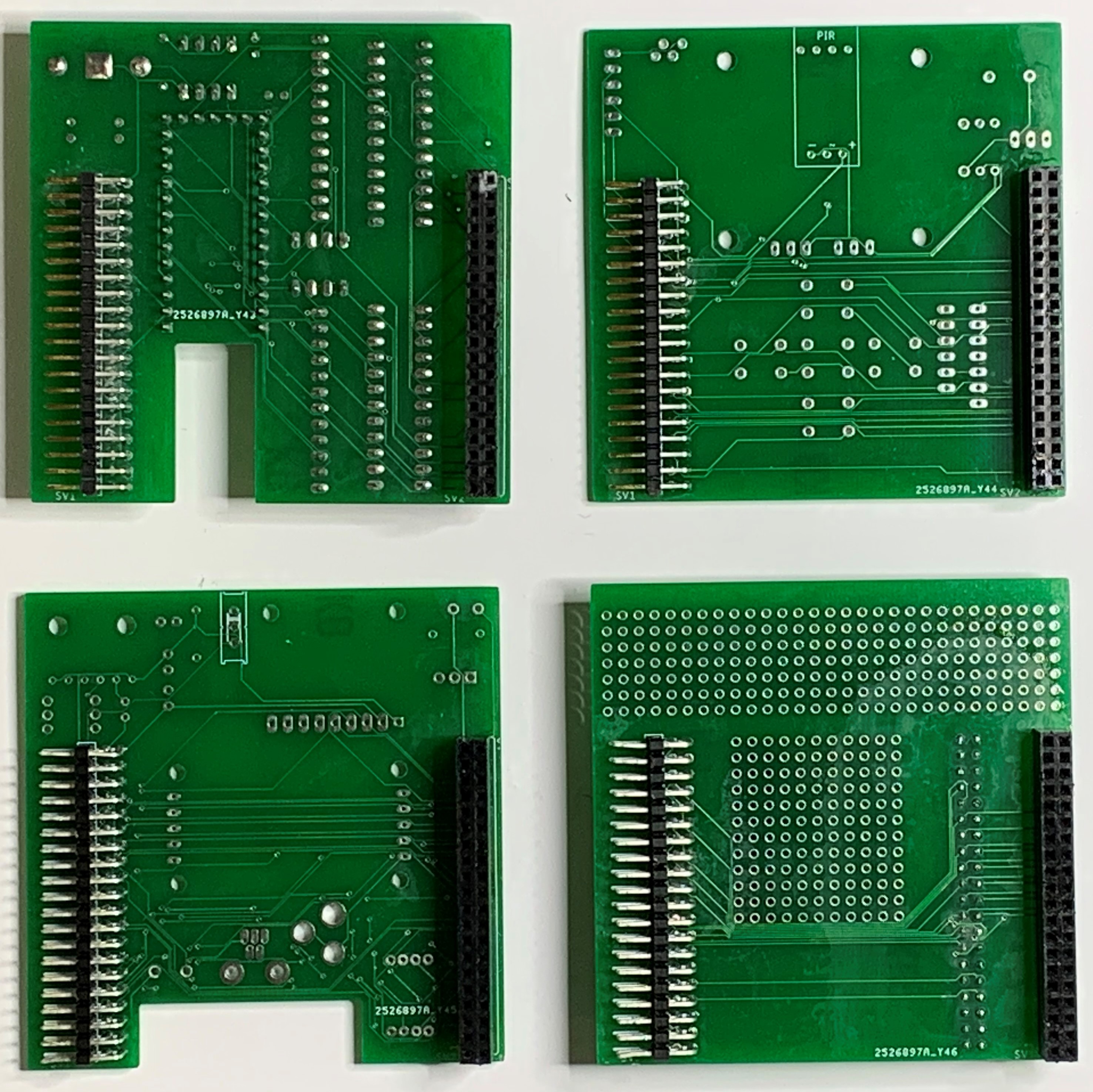
Overview We'll assemble the boards that comprise the Aduino M4 Cube one a time and then test the circuits on each. Below you can see the both the top-side (left screenshot) and bottom-side (right screenshot) views of the four boards that comprise the M4 Cube. In the two screenshots the boards are numbered 1 to 4: top left, top right, bottom left and bottom right. Board 1 is fully assembled with the Adafruit ItsyBitsy M4 Express microcontroller module. Once assembled together as a 3" x 3" cube, the top-sides become the exterior and the bottom-sides become the interior to the M4 Cube. However, before we do that we really should perform a continuity test with all four unpopulated boards connected together. Below right is a video showing the four boards connected together. Viewed from the top-side of any board, there is a female receptacle on the left and a male plug on the right. Of course you can only see where the pins poke through from the bottom-side to the top-side (the connectors are on the bottom-side of the boards).
Getting Power On the bottom-side of any board we see Pin 1 of the female connector is on the bottom left (the SV2 connector in Bd. 1 Schematic A is intentionally upside down to match the M4 uC). Pins 4 and 3 provide power.
4 Boards Top-side View 4 Boards Bottom-side View
We'll Test the Microcontroller First with a Couple of LEDs From Schematic A of Board 1, we can see connector SV2's pins 4 and 3 provide 3V3 and GND, respectively. We can connect a pair of jumper wires from the female connector to a breadboard to perform a simple test of the uC. If you don't have an RGB LED handy (maybe you have yet to order it from Adafruit/Digikey), use 3 LEDs and 3 current-limiting resistors. In the left adjacent video, you can see 3 LEDs as well as an RGB LED below them. The x_3_LEDs_Blink.ino sketch cycles through the 3 LEDs. We'll test the RGB when we finish Board 1 and move onto Board 2.
I2C, Pull-up Resistors, Real Time Clock (RTC) We fully assembled Board 1 which included the RTC. The real time clock is based on the Adafruit DS1307 RTC breakout board. The IC2 8-pin IC socket is for two pull-up resistors for your I2C circuits which includes the RTC. Try a 2.2k ohm resistor between pins 1 & 4 and another between pins 8 & 5, then start up your Arduino IDE, click "File | Examples | RTClib" and run the "ds1307 sketch". If you cannot find the library containing the examples, consider downloading it from here and dropping it in "C:\Users\YourName\OneDrive\Documents\Arduino\libraries". Do note that it's best to unzip the file to reveal the "RTClib-master" folder which historically must be renamed to "RTClib" to remove the "-master" component of the folder name. It would probably be a good idea to right-click on the Arduino "libraries" folder and choose "Send to | Desktop (create shortcut)" because you'll be dropping other libraries there, too. Under "Tools", ensure "Serial Monitor" is running; you should see the current date and time. This tests the I2C circuit for this board but not necessarily the other three boards. We'll get there eventually. If the time reported in Serial Monitor does not match that of your PC, power off your M4 Cube, remove the battery from the holder, download the RTC program again to the M4 Cube and check the time. If all is well reinstall the battery while the M4 Express module is running. Repower the unit to ensure the battery can hold the correct time.
Ok, let's move onto Board 2 now that Board 1 checks out. If you have issues, don't hesitate to email me at prefontDon@gmail.com or donp@networkHorizons.com.. |
![]()
Tags: Arduino-type Microcontroller, ATsamD51 Cortex M4
![]()