![]()
|
Test Your Cube M4: Board 2 |
| Circuit Tests (click .gif for video) | Test: I2C, OLED, RGB LED, Buzzer |
|
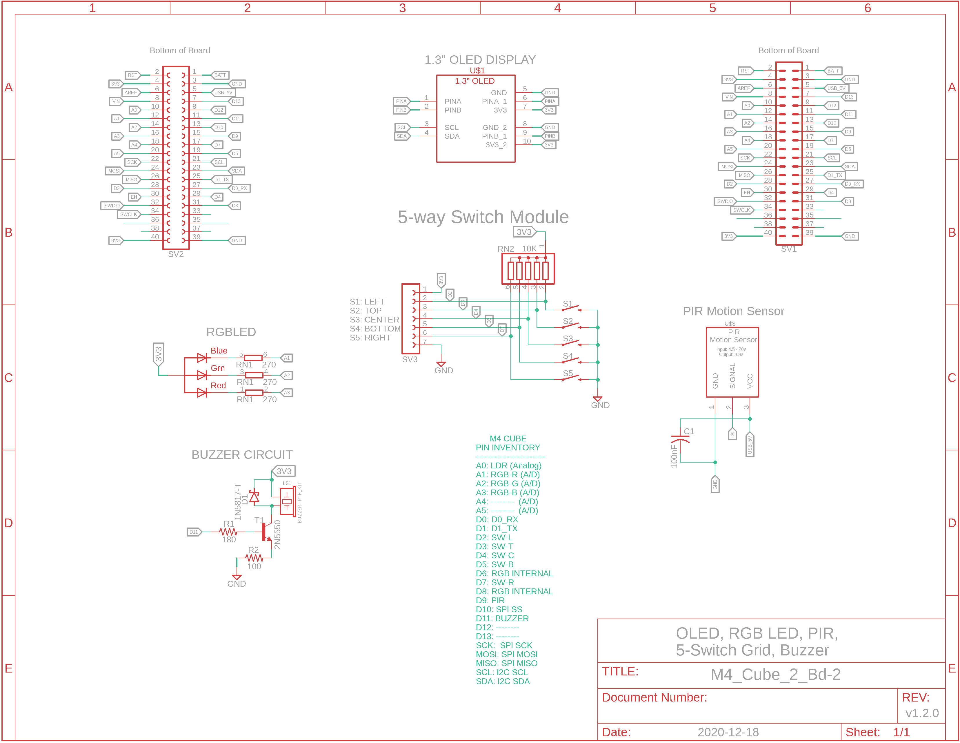
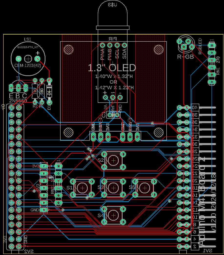
Eagle CAD: System Bd. 2 Schematic A
Eagle CAD: System Bd. 2 Schematic B
Video: OLED.ino Sketch
Video: 3_LEDs_Blink.ino Sketch
Video: Buzzer_05b.ino Sketch
|
Using uC Pin Resources The M4 Express microcontroller module pins are connected to all 4 boards. The right-most male connector on Board 1 is connected to the female connector on Board 4 (on its right) but not to the uC on Board 1 because this would create a loop which could have some odd effects. Dip switches SW1 and SW2 break the connection between the uC and the board connectors. With all of the dip switches in the OFF position (to the right), you can enable only the circuits of interest. This can simplify testing each circuit as you add a board to the Cube. For example, if you choose to not use the PIR or the LDR, you could open the circuit's dip switch and then run a jumper from the corresponding pin in SV3 or SV4 to a breadboard or to the development section of Board 4; your choice. In other words, you can use the uC pin for some other purpose.
Test All of Your I2C Devices: Each time we solder in a new circuit we test it. We should also build an inventory of addresses for all of the I2C devices. This will help us in the event of an address collision that won't permit something to run. The sketch of interest for you to run is x_I2C-Scanner.ino. - The RTC real time clock is at address 0x68 - The Banggood SSD1306 1.3" 128x64 OLED display is at address 0x3C. (A common Amazon.com offshore SH1106 OLED display is at address 0x3D.) - The BME280 is at address 0x77
1.3" 128x64 OLED How do you tell the Banggood OLED from the offshore one? Both are pinned out VDD, GND, SCL, SDA from left to right but the Banggood unit has round mounting holes whereas the offshore unit has oval ones. Note that you can use other 4-pin OLEDs, too. You will need to jumper PinA and PinB appropriately (VCC and GND) on Board 2 under the OLED. I would recommend installing the male jumper pins on the bottom of the board (inside the Cube). As you can see in the adjacent .gif file (click it for a larger .mp4 video file), we are running Adafruit's OLED test file.
I loaded the "ssd1306_128x64_i2c.ino" file found in the Arduino IDE under "File|Examples|Adafruit SSD1306" and made a few changes: - line 30: changed "#define OLED_RESET 4" to "#define OLED_RESET -1" - line 59: changed "if(!display.begin(SSD1306_SWITCHCAPVCC, 0x3D)) {" to "if(!display.begin(SSD1306_SWITCHCAPVCC, 0x3C)) {" These two lines will advise the driver there is no separate digital line to handle Reset and it will also change the I2C address from 0x3D to 0x3C. The file has been saved to x_OLED_4-Wire_SSD1306.ino.
Board 2 RGB LED Test & 5-Switch Matrix While waiting on my common anode RGB LED to arrive, I chose to install 3 LEDs on the top of Board 2 that would behave as if they were an RGB LED. Run the sketch x_3_LEDs_Blink.ino to test them/it. We'll use the RGB to test the 5 switches: Left, Top, Center, Bottom and Right. Each key press will yield a colour combination unique to that key. Upload the test file, x_Switches5_LEDs.ino to test the switches and the RGB LED again.
Buzzer Circuit To test the buzzer circuit using an existing sketch (modified slightly), you'll need to not just solder the buzzer circuit but also part of the 5-switch keypad circuit. This way whenever you press the left-most momentary switch, the red LED at the top of the board will illuminate and a short melody/tone will play on the buzzer. The sketch is x_Buzzer_02.ino. We'll finish assembling the 5-switch keypad and test more of the switches using sketch x_Buzzer_05b.ino
|
![]()
Tags: Arduino-type Microcontroller, ATsamD51 Cortex M4
![]()