![]()
|
Test Your Cube M4: Board 3 |
| Circuit Tests (click .gif for video) | Test: LDR, PIR, microSD, Quad 7-Segment LED Backpack |
|
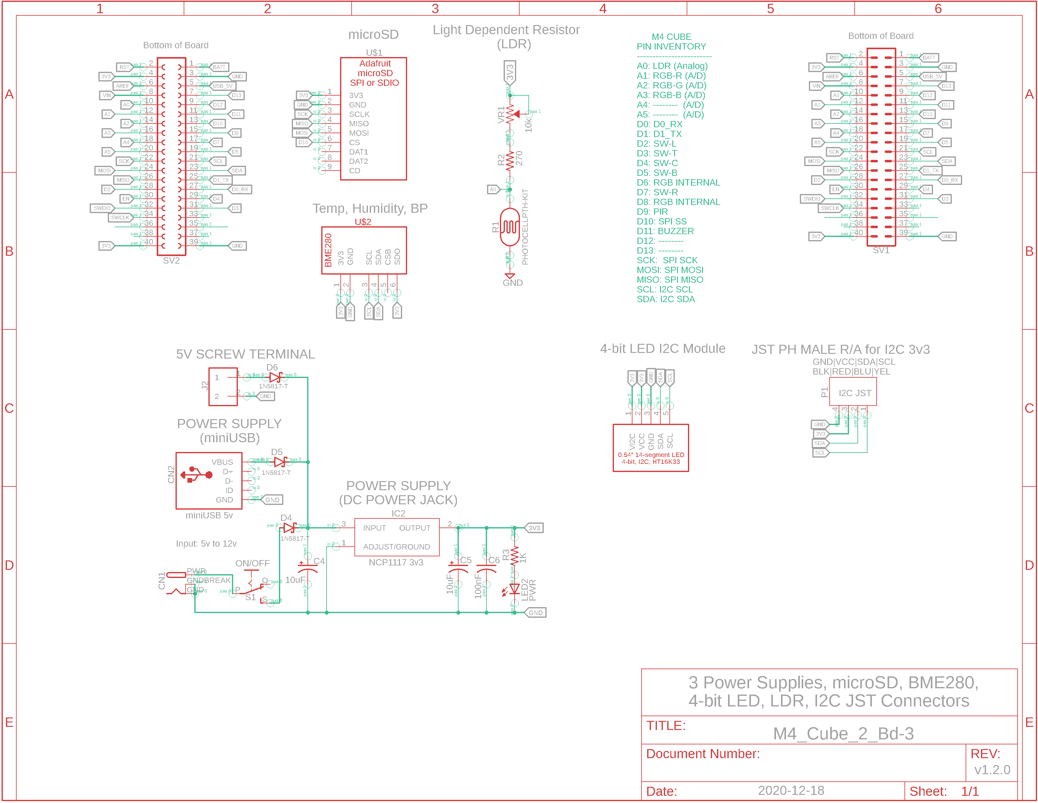
Eagle CAD: System Bd. 3 Schematic A
Eagle CAD: System Bd. 3 Schematic B
PIR Motion Detector Test
BME280 Test (Click for a short video)
PIR Motion Sensor & Micro-SD Test (Click for a short video)
LDR Test (Click for a short video)
Quad 7-Segment LED Module (Click for a short video)
|
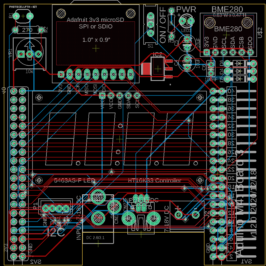
Power Power is provided (when not programming the M4 uC via a micro USB cable) via: - a barrel jack (2.5mm ID, 5.5mm OD, 12mm length, 3.5mm gap) 7v to 18v DC output - a miniUSB connector (5v DC) - a two-wire terminal block ( 7v to 18v DC) All 3 feeds protect the NCV1117 3.3v regulator each with a 1N5817-T low-drop (0.45v) diode but that is all there is for protection so please DON'T provide more than one source of power at a time to the Cube. In the enlargeable(?) screenshot below, you can see all 3 power inputs with the barrel jack being employed. M4 Cube Power
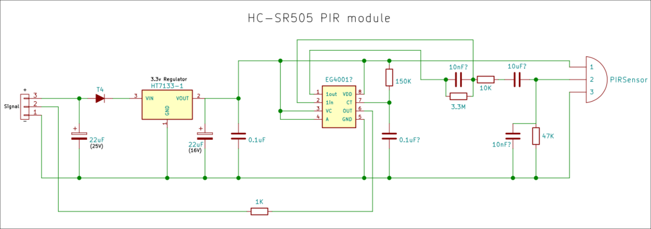
PIR Motion Sensor Pin A3 is used in ADC mode to read the middle PIR pin which outputs a 3.3v high when it senses motion. Be advised that it must receive 5v on its "+" pin or it may not work. We use the M4's 5V pin for the power. Load up the new x_PIR_02.ino sketch to test the PIR. The red LED illuminates for a predefined duration once the PIR notices activity. The minimum time that it stays high (even though activity has ceased) is about 7.5 seconds which can be seen if you have Serial Monitor running. You can see the red LED illuminate when it detects motion in the adjacent PIR video. Another file to be used for testing the PIR and OLED is Weather_Inside_M4_g.ino. Here's some info I found on the PIR motion sensor chip. The module is sold by Banggood. I also found a schematic someone drew based on their best guess using both the module and the chip vendor. Having an output drive for 7 to 8s is way too long and I would prefer a much lower value. If anyone figures out how to modify the module so it reliably outputs a 3v3 signal for a shorter time before re-arming, please let donp@NetworkHorizons.com know.
BME280 Sensor The next test uses portions of the "Weather_Inside_SD_Tone_Flash_2h.ino" file to test both the BME280 Temperature/Humidity/Barometric Pressure sensor as well as the OLED we tested earlier. Content will also go to the Serial Monitor running at 9600bps (default). The needed test file is x_BME280_OLED_Test.ino. Upload it to your M4 Cube. Expect the display to blank briefly every 2.5 seconds. Breathe directly on the BME280 board and you should see both the Serial Monitor and OLED display reflect the change in temperature and humidity as it does in the short video when we used compressed air on the BME280. BME280 Temperature/Humidity/Barometric Pressure sensor uses I2C so we can be fairly certain there are no I2C address collision if it's working fine.
Micro-SD Board The Adafruit ItsyBitsy M4 Express board uses the Microchip ATSAMD51G microcontroller which has many more I/O lines than the original ATmega328P. As such, some are labelled by function and not by digital/analog number. As an example with the old controller, A5 and A4 were available for I2C's SCL and SDA, respectively. A5 and A4 are ordinary pins on the new controller so you need to use the pins labelled as SCL and SDA that are adjacent to D5. SPI pins on the old controller were numbered D10(SS), D11(MOSI), D12(MISO) and D13(SCK). On the new controller they are *, MO, MI and SCK. Historically we used D10 for the SS select signal so we'll do the same in our test code. The Arduino test file, x_BME280_OLED_RTC_SD_Test.ino, continues with the previous test modules you've worked through and has an added test for the microSD card module, too. You may notice in the file that all of the text printable by the Serial Monitor is prefaced by "F()". This is to move the text out of global variables memory and into regular memory. Failure to do so resulted in a "Low memory resources can lead to unstable operation" or something like that in the older ATmega328P uC. This is no longer a concern with this big memory uC but we'll keep up the good habit. In the test file the data is written to the SD card every 5 seconds. You will see "!" flash to the right of the current time on the OLED after the data is written to the microSD card. You will probably want to change the timers so that the screen is displayed for 10s (when movement occurs via the PIR) and the file is written every minute.
LDR (Light Dependent Resistor) Analog pin A4 carries the signal from the LDR and converts it to a digital value between 0 and 255. Use sketch x_LDR_3LEDs_A0.ino. With Serial Monitor running, turn the potentiometer VR1 fully clockwise while light is shining on the LDR. Your highest reading should be in the 800s, fully counter-clockwise the lowest reading should be in the 100s. As part of your design, the LDR could determine darkness from nighttime or a full eclipse or an intergalactic invasion... your choice.
5 Switch Matrix We'll use the RGB to test the 5 switches: Left, Top, Center, Bottom and Right. Each key press will yield a colour combination unique to that key" - Left: red - Top: Purple - Center: Green - Bottom: White - Right: Blue You will need the following jumpered on: A1, A2, A3, D5, D6, D7, D8, D9. Upload the test file, x_Switches5_LEDs.ino to test the switches and the RGB LED again.
Quad 7-Segment Module (I2C Backpack) You will need the Adafruit library for this I2C device. Upload the HT16K33.ino sketch to test your display. For the final test of all systems, upload x_Weather_Inside_M4_h.ino
At this point, all of the circuits should be working fine. If any one is not, consider disabling the Aduino resource by moving the switch from left to right. You can then build the circuit on a breadboard and use jumper wire to connect to the female resource pin to see if it works properly when not actually on the PCB. |


![]()
Tags: Arduino-type Microcontroller, ATsamD51 Cortex M4
![]()